Gunsight

A sight and microcontroller technology, applied in the field of sight, can solve the problem of not being able to quickly and accurately aim at the target

Active Publication Date: 2011-06-22
ASIA OPTICAL CO INC
View PDF4 Cites 11 Cited by
  • Summary
  • Abstract
  • Description
  • Claims
  • Application Information

AI Technical Summary

Problems solved by technology

[0005] The technical problem to be solved by the present invention is to provide a sight that can clearly see the line of sight and the ballistic trajectory in the dark environment in view of the defect that the above-mentioned sight in the prior art cannot quickly and accurately aim at the target in a dark environment Compensation lines for fast targeting

Method used


Image

  • Gunsight
  • Gunsight
  • Gunsight

Examples


Embodiment Construction

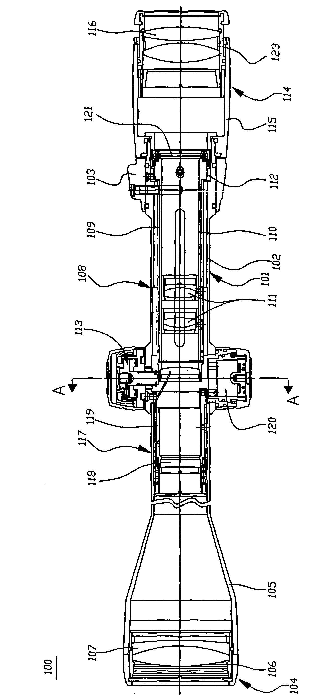
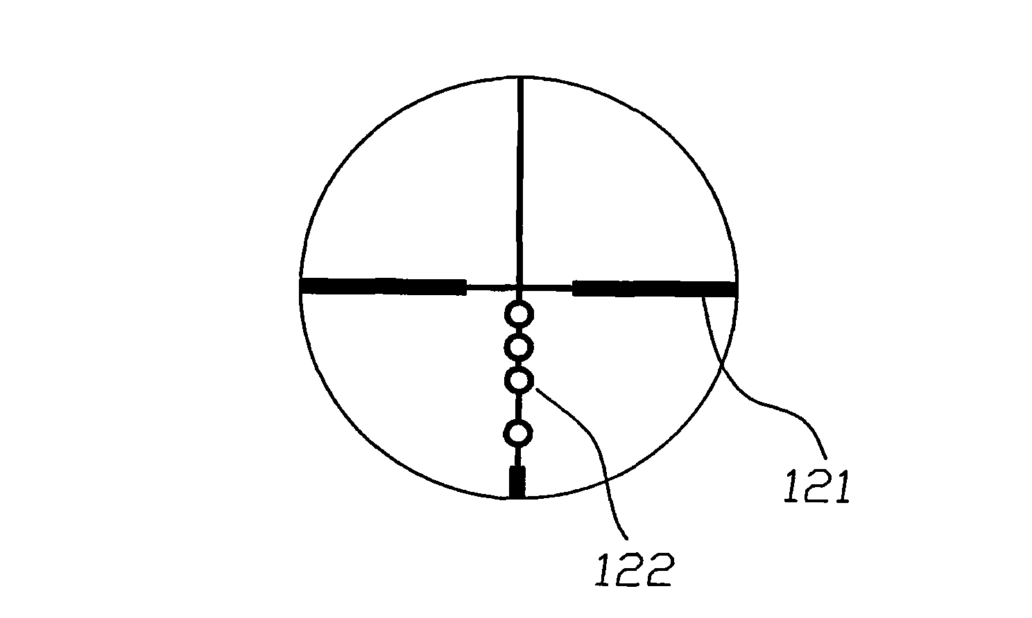
[0035] Such as Figure 4 As shown, the sight 200 of the present invention includes: a housing 201, an objective lens group 202, an upright group 203, a bullet correction group 204, an eye group 205, a focus adjustment group 206, and a display group 207, combined Figure 5 As shown, the display group 207 includes a cross-shaped sight line 208 and a ballistic compensation line 209 made of light-emitting devices. The ballistic compensation line 209 includes a plurality of ballistic compensation positions 209a to 209d, corresponding to different distances, such as 200 yards. , 300 yards, 400 yards, and 500 yards. The light emitting device may be an organic light emitting diode (Organic Light Emitting Diode, OLED for short). It should be noted that the line of sight 208 can also be made of a light-emitting device.

[0036] The display group 207 also includes a circuit driving unit 211 for driving the different ballistic compensation positions 209a-209d of the ballistic compensation li...


PUM


Abstract

The invention relates to a gunsight on a shooting gun. The gunsight comprises a display set composed of trajectory compensation lines made from luminescent devices. By using the gunsight, operators can clearly see a line of sight and the trajectory compensation lines even in dark environment, so that operators can aim at targets rapidly and accurately.

Description

Technical field [0001] The present invention relates to a shooting gun, and more specifically, to a sight on the shooting gun. Background technique [0002] During the shooting process, because the bullet was affected by gravity and deviated from the target, the bullet’s flight path was actually a parabola. In order to accurately hit the target, different aiming heights must be used when shooting targets at different distances. At present, some sights have adopted a ballistic compensation line combined with the line of sight. figure 1 with figure 2 This shows the sight in the prior art. Reference figure 1 with figure 2 , The sight 100 includes: a housing 101, including a cylindrical body 102, and a magnification adjustment ring 103 for accommodating related components; an objective lens group 104, including an object outer barrel 105 connected to the front end of the housing 101, set in The objective lens chamber 106 in the objective outer tube and the multiple objective lens...

Claims


Application Information

Patent Timeline
Patent Type & Authority Applications(China)
IPC IPC(8): F41G1/32F41G1/16
Inventor 唐家其陈东庆
Owner ASIA OPTICAL CO INC
Why Eureka
Try Eureka