
A fast aiming device and method for a waveguide antenna

A waveguide antenna and aiming device technology, applied in antennas, electrical components, etc., can solve the problems of poor reliability of measurement data, different accuracy, lack of quantitative measurement, etc., and achieve easy and fast aiming, easy calibration, and wide application prospects Effect

Active Publication Date: 2017-07-28
中国人民解放军63660部队
View PDF4 Cites 0 Cited by
  • Summary
  • Abstract
  • Description
  • Claims
  • Application Information

AI Technical Summary

Problems solved by technology

Its advantages are intuitive and convenient, and quick operation, but the accuracy of visual inspection varies from person to person, lack of quantitative measurement, and the reliability of measurement data is poor
[0010] The above two methods have their own advantages and disadvantages. Therefore, it is of practical significance to find a convenient and quick aiming method that can provide intuitive quantitative and high precision for measuring the aiming of waveguide antennas in the microwave radiation field.

Method used


Image

  • A fast aiming device and method for a waveguide antenna
  • A fast aiming device and method for a waveguide antenna
  • A fast aiming device and method for a waveguide antenna

Examples


Embodiment Construction

[0052] The present invention will be further described in detail below with reference to the accompanying drawings and specific embodiments, taking the aiming of a rectangular waveguide horn antenna as an example.

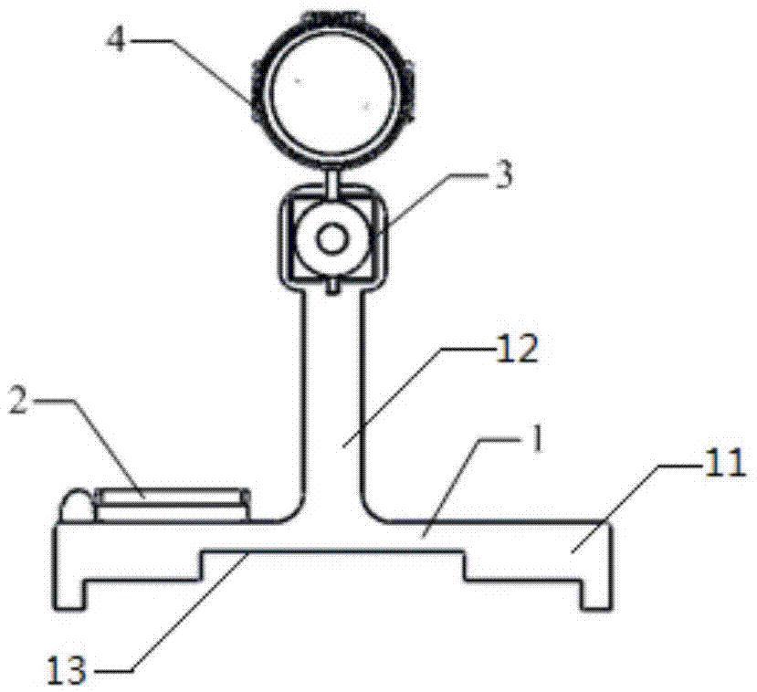
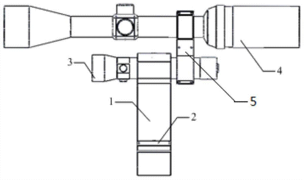
[0053] Figure 1a and Figure 1b It is a schematic diagram of the composition of the fast aiming device of the waveguide antenna of the present invention. The device includes an aiming base 1, an angle indicating device 2, a laser pointer 3 and an optical sight 4, and the laser pointer 3 and the optical sight 4 together constitute an aiming point indicating device.

[0054] Among them, the bottom of the aiming base 1 can be quickly connected to the waveguide antenna by setting a slot 13 that closely matches the outer wall of the waveguide antenna (such as a rectangular waveguide); , to easily realize the quick fit connection with the reference physical plane.

[0055] The angle indicating device 2 is fixed on the upper surface of the bottom surface of the aiming ...


PUM


Abstract

The invention discloses a fast aiming device for a waveguide antenna, which includes an aiming base, an angle indicating device and an aiming point indicating device. The aiming base is an inverted T-shaped structure, which includes a base and an installation shaft vertically connected to the base. The surface is flat, and the lower surface of the base is recessed with a card slot, which is connected with the waveguide antenna; the angle indicating device is fixed on the upper surface of the base; the aiming point indicating device includes a laser pointer and an optical sight; the laser pointer is set on the installation shaft On the upper end, the optical sight is arranged directly above the laser pointer, the laser pointer is provided with an optical axis adjustment device, and the optical sight is provided with a visual axis adjustment device. The invention can realize fast aiming of visible aiming points at different distances on the premise of ensuring the aiming accuracy of the waveguide antenna in the measurement of the microwave radiation field, and improve the convenience of aiming the waveguide antenna in the measurement of the radiation field.

Description

technical field [0001] The invention relates to the technical field of microwave radiation field measurement, in particular to a fast aiming device for a waveguide antenna and a method thereof. Background technique [0002] Waveguide antennas (such as open waveguides and horn antennas) are directional radiation antennas. They have the characteristics of simple structure, moderate gain, and the main axis of radiation coincides with the physical axis. They are commonly used microwave transmitting and receiving antennas. In the microwave radiation field measurement, the aiming accuracy of the waveguide antenna has a great influence on the measurement results and measurement uncertainty. [0003] In the radiation field measurement, the aiming of the waveguide antenna mainly includes two aspects: [0004] (1) The polarization relationship between the receiving antenna and the transmitting antenna; [0005] (2) The angular relationship between the receiving antenna and the trans...

Claims


Application Information

Patent Timeline
Patent Type & Authority Patents(China)
IPC IPC(8): H01Q3/00
Inventor 杨猛晏峰张永栋景洪李治国
Owner 中国人民解放军63660部队
Learn More