Vortex-induced vibration test device for stand pipe under bidirectional shear flow and bidirectional ladder shear flow

A two-way shear flow and two-way ladder technology, applied in the field of marine engineering, can solve the problems of inability to simulate the vortex-induced vibration of the riser in the stepped flow field, the difficult vortex-induced vibration test, and the small distance of the test section. Ease of installation and increased accuracy

Active Publication Date: 2011-06-29
SHANGHAI JIAO TONG UNIV
View PDF2 Cites 20 Cited by
  • Summary
  • Abstract
  • Description
  • Claims
  • Application Information

AI Technical Summary

Problems solved by technology

After analysis, the shortcomings of this test technology are: 1. Generally, it can only simulate the vortex-induced vibration of small-scale pipe fittings, and it is difficult to effectively carry out the vortex-induced vibration test under the real Reynolds number
2. Due to the limitation of the length of the deep water tank of the towed marine engineering, the distance of the test section obtained is relatively small, and the measured test data is less
3. Generally, only the vortex-induced vibration of the standpipe in the uniform flow field can be simulated, and the vortex-induced vibration of the standpipe in the stepped flow field cannot be simulated

Method used


Image

  • Vortex-induced vibration test device for stand pipe under bidirectional shear flow and bidirectional ladder shear flow
  • Vortex-induced vibration test device for stand pipe under bidirectional shear flow and bidirectional ladder shear flow
  • Vortex-induced vibration test device for stand pipe under bidirectional shear flow and bidirectional ladder shear flow

Examples


Embodiment Construction

[0034] The embodiments of the present invention are described in detail below. This embodiment is implemented on the premise of the technical solution of the present invention, and detailed implementation methods and specific operating procedures are provided, but the protection scope of the present invention is not limited to the following implementation example.

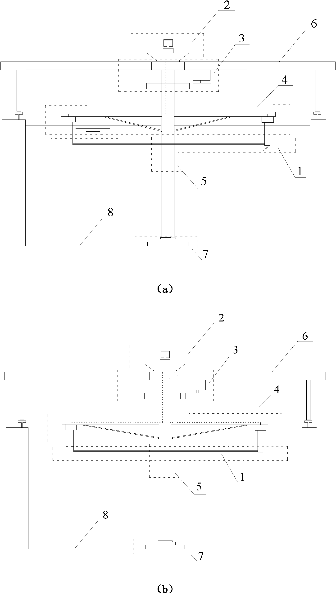
[0035] Such as figure 1 As shown, this embodiment includes: a riser model mechanism 1, a measurement and analysis system platform module 2, a drive module 3, a top cantilever module 4, a cylindrical shaft segment module 5 and a bottom support module 7, wherein: the riser model is passed through a special The designed fixed end is suspended and fixed under the top cantilever module 4, and the bottom support module 7, drive module 3, and top cantilever module 4 are vertically connected through the cylindrical shaft segment module 5 vertically placed in the deep water tank of the ocean engineering, and the bottom supp...


PUM


Abstract

The invention relates to a vortex-induced vibration test device for a stand pipe under the bidirectional shear flow and the bidirectional ladder shear flow, and belongs to the technical field of marine engineering. The vortex-induced vibration test device comprises a stand pipe model mechanism, a measurement and analysis system platform module, a drive module, a top cantilever module, a cylinder shaft segmentation module and a bottom supporting module, wherein the fixed end of the stand pipe model mechanism is suspended and fixed below the top cantilever module; the cylinder shaft segmentation module is perpendicularly placed in a marine engineering deep pool and is respectively and perpendicularly connected with the bottom supporting module, the drive module and the top cantilever module; the bottom supporting module is fixedly arranged on the lifting bottom of the marine engineering deep pool; the drive module is respectively connected with the cylinder shaft segmentation module and the top cantilever module and is used for outputting power; the left end and the right end of the top cantilever module are respectively connected with the cylinder shaft segmentation module; and the measurement and analysis system platform module is respectively connected with the stand pipe model, the top cantilever module and the bottom cantilever module. The vortex-induced vibration test device is convenient to install, update and change, and meets different functional requirements.

Description

technical field [0001] The invention relates to a device in the technical field of marine engineering, in particular to a vortex-induced vibration rotation testing device for a flexible pipe model placed horizontally in a deep pool of marine engineering under bidirectional shear flow and bidirectional stepped shear flow. Background technique [0002] According to the knowledge of fluid mechanics, when a columnar structure is placed in a certain speed of incoming flow, alternate vortices will occur on both sides of it. Associated with the creation and discharge of vortices, the column is subjected to lateral and flow-wise pulsating pressures. If the column is elastically supported at this point, the pulsating fluid forces will induce vibrations in the column, which in turn will change the structure of its wake. This fluid-structure interaction problem is called vortex-induced vibration. For example, under the action of ocean currents, vortex-induced vibrations will occur on...

Claims


Application Information

Patent Timeline
Patent Type & Authority Applications(China)
IPC IPC(8): G01M7/02G01M10/00
Inventor 付世晓任铁杨建民李琳
Owner SHANGHAI JIAO TONG UNIV
Why Eureka
Try Eureka