Improved single-arm yarn carrier

A yarn guide device and single-arm technology, which is applied in textiles and papermaking, weft knitting, knitting, etc., can solve problems affecting the tension transmission of the mandrel and the tension spring, loosening or shaking of the yarn guide rod, and instability, etc., to achieve Ensure normal operation, avoid loosening, and reduce costs

Active Publication Date: 2011-07-06
陈仁惠 +2
View PDF10 Cites 8 Cited by
  • Summary
  • Abstract
  • Description
  • Claims
  • Application Information

AI Technical Summary

Problems solved by technology

Since the connection between the mandrel and the yarn guide rod is only pressed by a single screw from the screw lock, the yarn guide arm will swing extremely momentarily during the fast yarn feeding operation, which makes the yarn guide rod easy to loosen or break after a period of use. Shaking instability, coupled with the fact that the mandrel needs to cooperate with the tension mechanism at the same time to transmit the tension of the extension spring, makes the bending part at the end of the connecting piece in the hole at the bottom of the mandrel easy to slide and loosen, and there will be friction. Affects the tension transmission of the mandrel and the tension spring

Method used


Image

  • Improved single-arm yarn carrier
  • Improved single-arm yarn carrier
  • Improved single-arm yarn carrier

Examples


Embodiment Construction

[0031] In order to make your review committee members have a further understanding and understanding of the technical characteristics and the achieved effects of the present invention, the detailed descriptions are as follows with better embodiment diagrams and coordination:

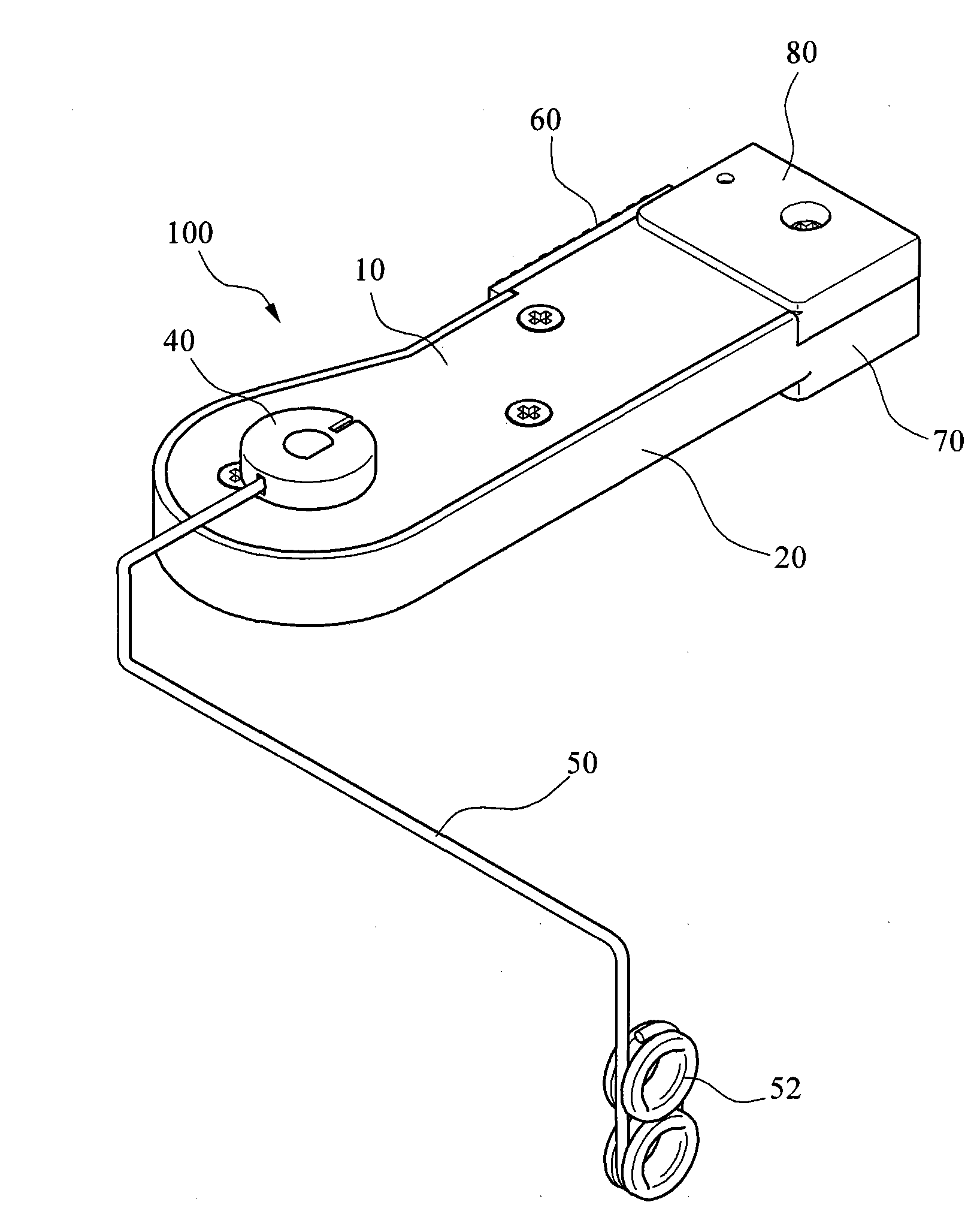
[0032] see figure 1 , is a perspective view of the first embodiment of the present invention, the single-arm yarn guide device 100 includes a housing composed of a cover 10 and a base 20, a pivoting device 30 (not shown in the figure), a connecting piece 40, a yarn guide arm 50 and an adjustment 60 pieces. One end of the base 20 is provided with a fastening seat 70 , and the cover 10 is extended with a seat cover 80 corresponding to the fastening seat 70 .

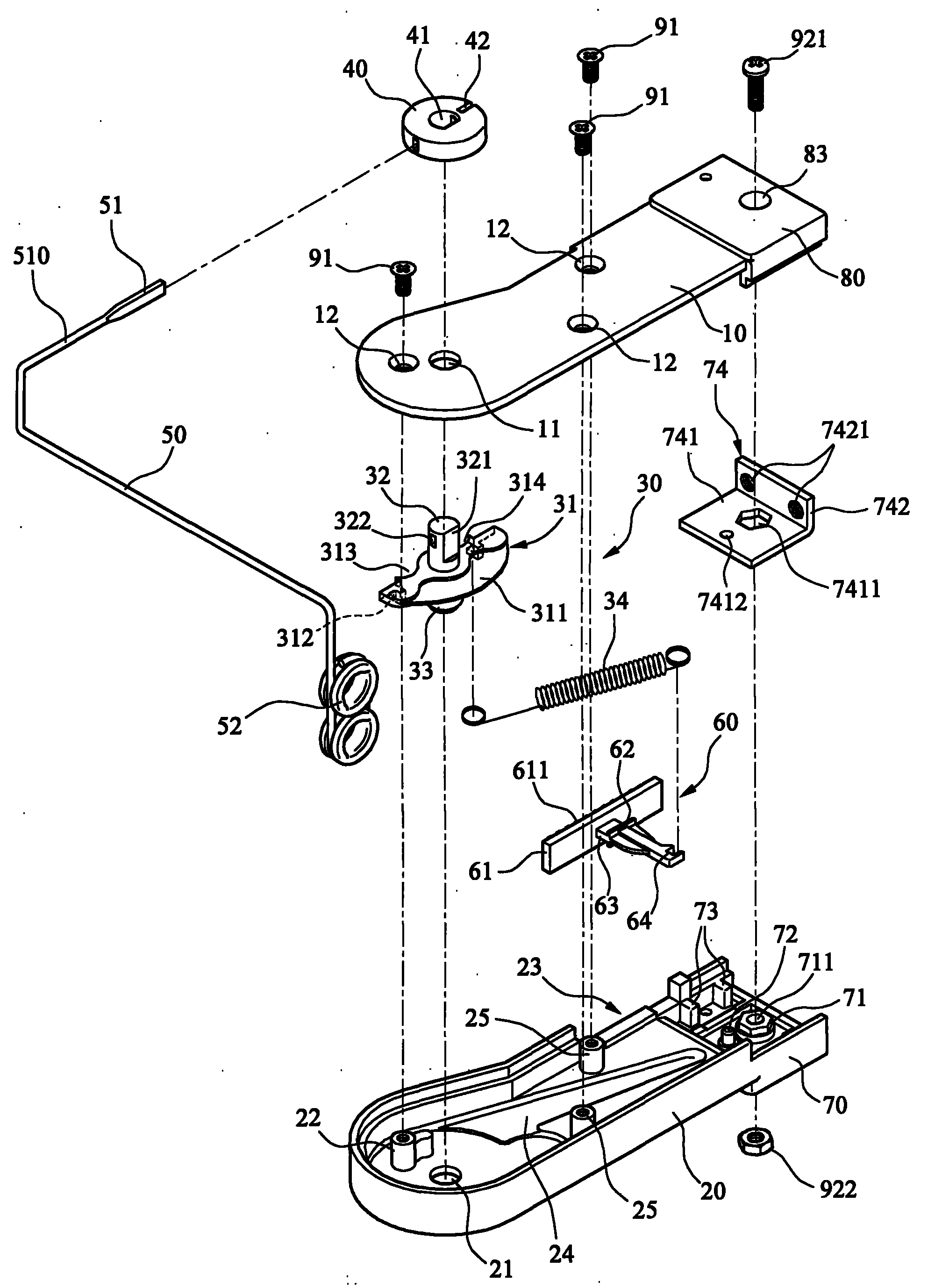
[0033] Such as figure 2 As shown in , it is a combined perspective view of the first embodiment of the present invention. The pivoting device 30 is arranged in the housing formed by the cover 10 and the base 20, and the pivoting device 30 includes...


PUM


Abstract

The invention provides an improved single-arm yarn carrier comprising a shell consisting of a cover body and a base, a pivoting device arranged in the shell, a connecting piece connected with the pivoting device, a yarn guiding arm connected with the connecting piece and a yarn guiding eye arranged at the free end of the yarn guiding arm, wherein the pivoting device comprises a swing member; the swing member is provided with a body, as well as a first pivot shaft and a second pivot shaft which are integrally extended out of the body; at least one hook rod is arranged on the body; a spring is connected between the hook rod and the base; the swing member is arranged in the cover body and the base in a pivoting manner through the first pivot shaft and the second pivot shaft; and after penetrating through the cover body, the first pivot shaft is connected with the connecting piece so that the swing member can be interlocked with and drive the yarn guiding arm arranged on the connecting piece to swing through the first pivot shaft.

Description

technical field [0001] The invention relates to a yarn guide device of a knitting machine, in particular to a single-arm yarn guide device. Background technique [0002] Press, the existing knitting machine guides the yarn into the yarn feeding device through a yarn guide device, and then performs subsequent quantitative or variable yarn feeding operations, such as Chinese Patent Publication No. CN1690283, which discloses a single-arm The yarn guide rod device has a base and a cover that are mutually covered and consolidated on the outside of the yarn guide rod device, and a swing mechanism drives the yarn guide rod (yarn guide arm). [0003] The swinging mechanism includes a mandrel and a yarn guide rod, the mandrel is passed through the shaft hole on the cover body and connected with the base by a tension mechanism. The upper part of the mandrel is provided with an axial screw hole and a positioning groove passing through the screw hole transversely, and a transverse hole...

Claims


Application Information

Patent Timeline
Patent Type & Authority Applications(China)
IPC IPC(8): D04B15/58
Inventor 陈仁惠陈佩莹陈伯霖
Owner 陈仁惠
Why Eureka
Try Eureka