Mould releasing and combining device for large steel form and assembling method thereof

A mold clamping device and a technology of steel formwork, which are applied in the connection parts of formwork/formwork/work frame, processing of formwork, formwork/formwork/work frame, etc., can solve the problem of time-consuming, labor-intensive and low-efficiency mold removal and mold clamping. and other problems, to achieve the effect of simple structure, improved work efficiency and safe connection

Active Publication Date: 2011-07-13
CHINA CONSTR THIRD ENG BUREAU GRP CO LTD
View PDF6 Cites 16 Cited by
  • Summary
  • Abstract
  • Description
  • Claims
  • Application Information

AI Technical Summary

Problems solved by technology

[0004] The purpose of the present invention is to provide a large steel formwork ejection and mold clamping device and its installation method, to solve the technical problems of the existing large steel formwork that are time-consuming and labor-intensive when withdrawing and closing the mold, and have low work efficiency

Method used


Image

  • Mould releasing and combining device for large steel form and assembling method thereof
  • Mould releasing and combining device for large steel form and assembling method thereof
  • Mould releasing and combining device for large steel form and assembling method thereof

Examples


Embodiment Construction

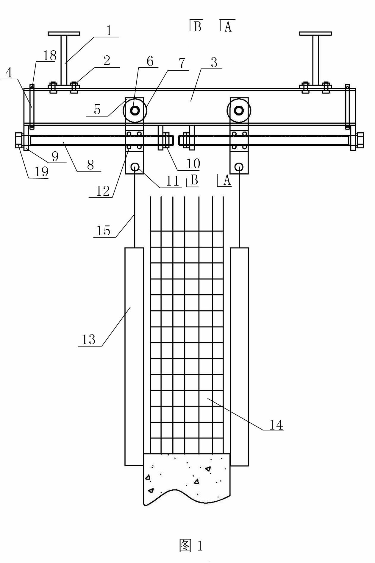
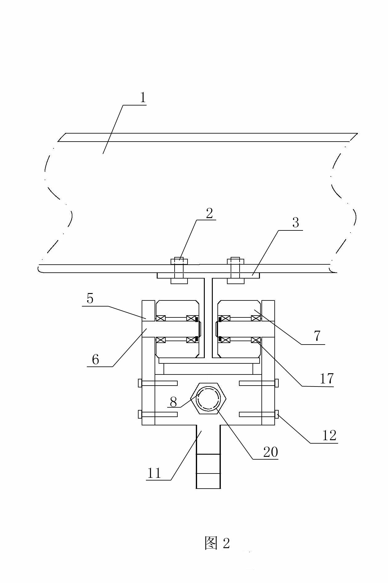
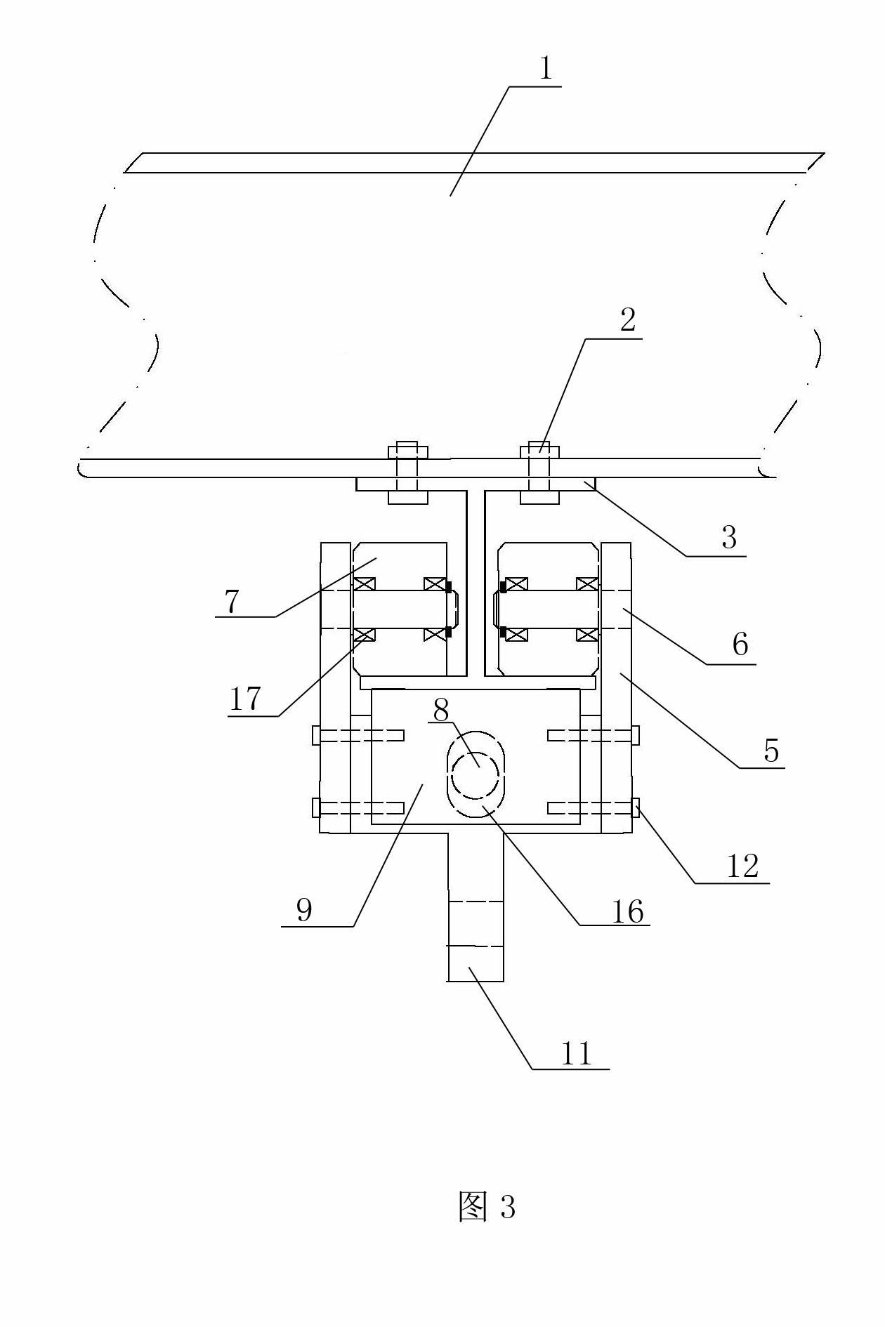
[0030] Examples see Figure 1 to Figure 4 As shown, a large steel formwork ejection and mold clamping device is connected to the lower chord section steel 1 of the steel platform through the connecting bolt I2, including a load-bearing rail 3 and at least one set of rollers 7, inverted T-shaped roller frames 11 and roller shafts 6 The pulley composed, the outer end of the horizontal side of the inverted T-shaped roller frame 11 is connected with a side plate 5, the side plate 5 is connected with a roller shaft 6, and the roller shaft 6 is equipped with a roller 7 through a bearing 17 , the rollers 7 are set on the load-bearing rail 3, and the outer end of the vertical side of the inverted T-shaped roller frame 11 is suspended with a pair of large steel formworks 13 parallel to each other through the suspension mechanism 15, and the large steel formwork 13 Located on both sides of the wall 14 to be poured, four screw fixing plates 9 with waist row holes 16 are respectively weld...


PUM


Abstract

The invention relates to a mould releasing and combining device for a large steel form. The device comprises a bearing rail, a pulley consisting of a roller, an inversed T-shaped roller frame and a roller shaft, wherein the roller is sleeved on the bearing rail; the inversed T-shaped roller frame is screwed with an adjusting screw rod which is fixed at the bottom surface of the bearing rail; the large steel form is connected to the vertical edge of the inversed T-shaped roller frame; and the adjusting screw rod and the screw hole on the roller frame rotate relatively by rotating the adjusting screw rod, and the pulley is driven to move along a profile steel rail, so that the large steel form hung under the pulley moves horizontally, and the effect of releasing or combining the mould of the large steel form can be achieved. The mould releasing and combining device has the advantages of simple structure, time and labor conservation and the like, and can be widely applied to mould releasing and combining of the large steel form by adopting a jack-up steel construction platform.

Description

technical field [0001] The invention relates to a device for withdrawing and clamping a large steel formwork and an installation method thereof. Background technique [0002] In the core tube concrete construction of modern super high-rise buildings, using a self-elevating large-scale steel platform will greatly increase the construction speed and reduce the construction cost. In the construction using this kind of self-elevating large-scale steel platform, when the large-scale steel formwork suspended under the steel platform is withdrawn and closed, human power or chain hoists are used to push or pull the hanger pulley, which is time-consuming and laborious, and the work efficiency is low. Low. This makes the ergonomics of the self-elevating large steel platform limited to a certain extent and cannot be fully utilized. [0003] Therefore, it is necessary to provide a large steel formwork ejection and clamping device to solve the above problems. Contents of the inventio...

Claims


Application Information

Patent Timeline
Patent Type & Authority Applications(China)
IPC IPC(8): E04G19/00E04G13/00E04G17/00E04G21/14
Inventor 张琨黄刚吴延宏张明黄王开强黄爽刘志茂
Owner CHINA CONSTR THIRD ENG BUREAU GRP CO LTD
Why Eureka
Try Eureka