
Mirror device

A technology of mirrors and reflective surfaces, applied in optical observation devices, mirrors, transportation and packaging, etc., can solve the problems of difficult observation, incoordination, and inability to identify mirrored objects, to eliminate parallax and quickly identify mirrored objects. The object, the realization of commercial effect

Inactive Publication Date: 2011-07-20
HONDA MOTOR CO LTD
View PDF8 Cites 0 Cited by
  • Summary
  • Abstract
  • Description
  • Claims
  • Application Information

AI Technical Summary

Problems solved by technology

However, there is a problem that the driver's brain cannot process the information when the driver's left and right eyes are not at the same height because the concave surface has a great influence on the parallax of the two eyes. , and it is difficult to observe, and may not be able to recognize the mirrored object for a moment

Method used


Image

  • Mirror device
  • Mirror device
  • Mirror device

Examples


Embodiment Construction

[0032] Hereinafter, a mirror device according to an embodiment of the present invention will be described with reference to the drawings.

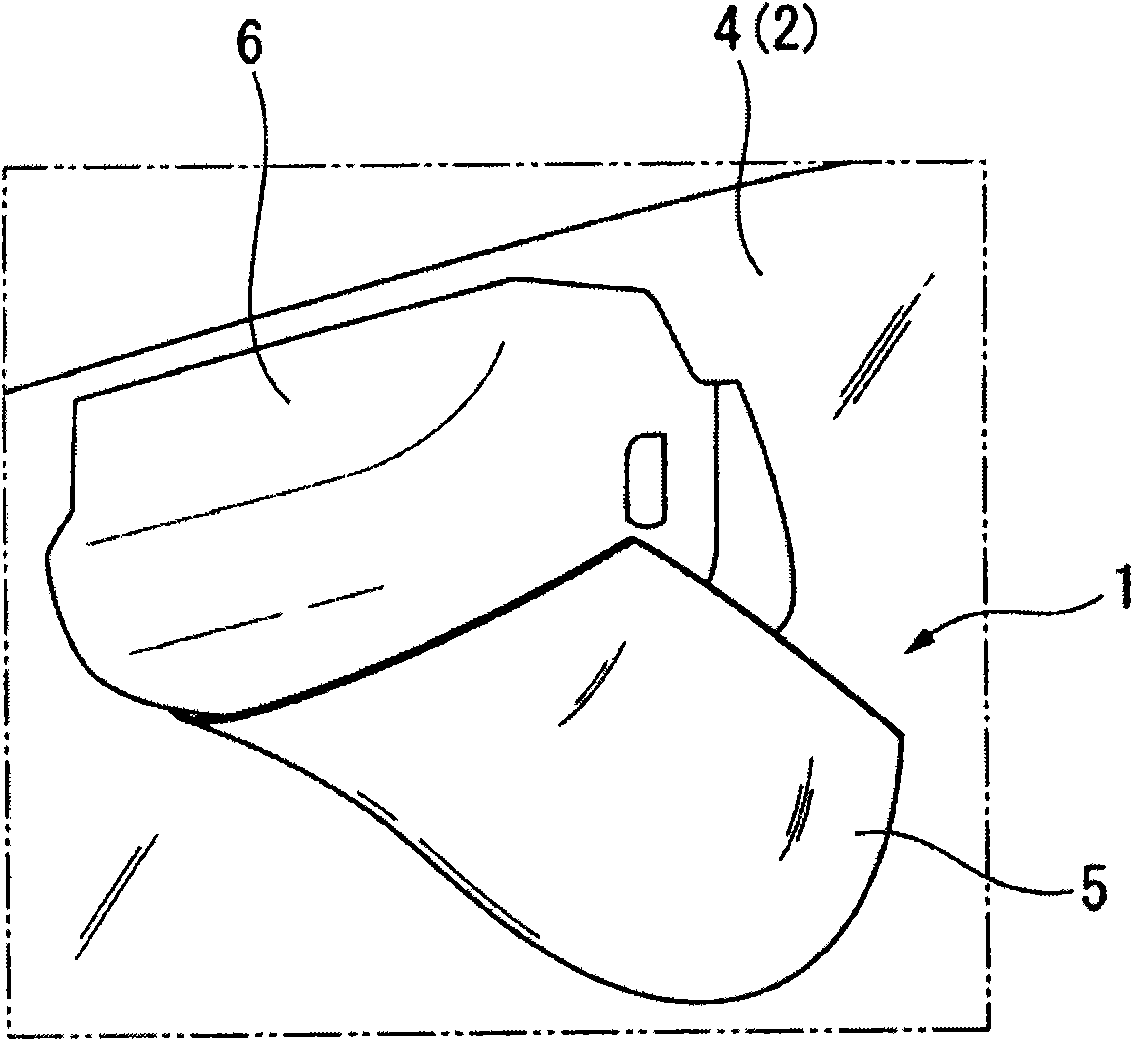
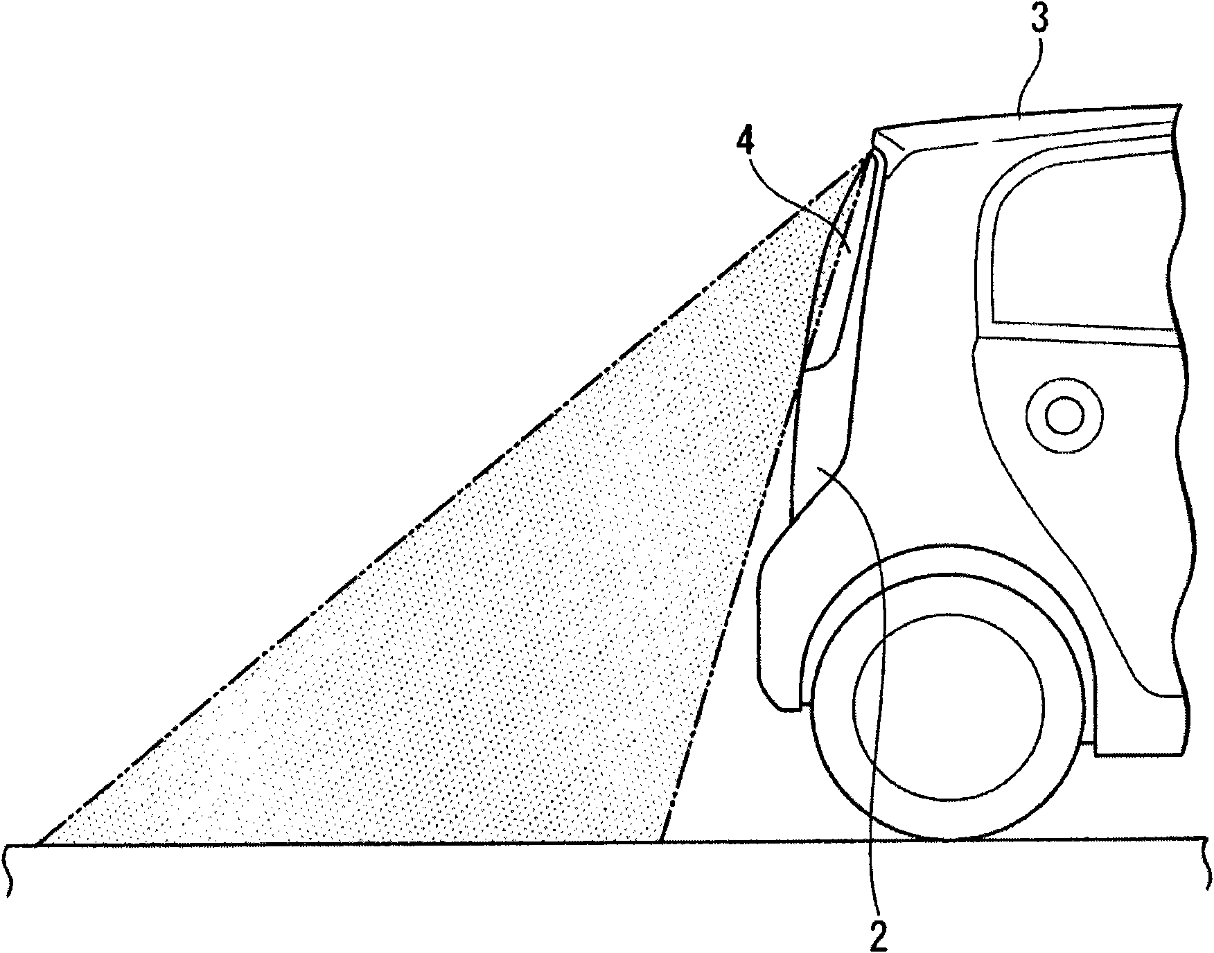
[0033] Such as figure 1 , figure 2 As shown, the reflector device 1 of this embodiment is arranged at the approximate center in the vehicle width direction above the rear window 4 of a vehicle 3 having a tailgate 2 such as a truck, and on the lower rear side of the rear window 4 that is not directly visible to the driver. The range can be visually recognized through the reflective surface 5 as a mirror image. In addition, in figure 1 In FIG. 2 , an example in which the reflective surface 5 is attached to the vehicle interior member 6 disposed above the rear window 4 on the vehicle interior side is shown.

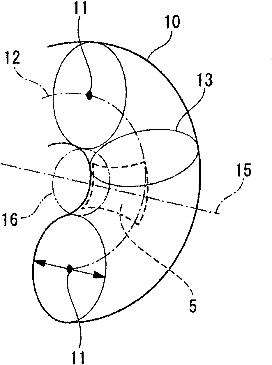
[0034] The reflective surface 5 has a curved surface that is concave in the vertical direction and convex in the horizontal direction, and is formed image 3 The so-called toroidal mirror surface of a part of the inner peripheral su...


PUM


Abstract

A mirror device includes a reflecting surface. The reflecting surface is arranged in a vicinity of a rear window of a vehicle. The reflecting surface includes a concave part in a longitudinal direction of the reflecting surface and a convex part in a lateral direction of the reflecting surface. A line passing through a center of a virtual circle defining the concave part is inclined relative to a virtual horizontal line extending in a vehicle width direction toward a side opposite to a driver seat in the vehicle width direction.

Description

technical field [0001] The present invention relates to a mirror device arranged near a rear window of a vehicle. Background technique [0002] Conventionally, a ground mirror capable of indirectly visualizing a position that a driver cannot directly visually recognize has been known as a mirror device. Convex mirrors that can obtain a wide range of mirror images through small reflecting surfaces are often used on the ground mirrors. However, when convex mirrors are used, they become inverted mirror images, making it difficult for users to recognize them. In some cases, there is a problem that the visible range on the side closer to the vehicle is narrower than that of the concave mirror. Therefore, in recent years, devices using a so-called toroidal surface having a convex surface in the x-axis direction and a concave surface in the y-axis direction as a mirror surface have been proposed (for example, refer to Patent Documents 1 and 2). With this torus, a wide-range mirro...

Claims


Application Information

Patent Timeline
Patent Type & Authority Applications(China)
IPC IPC(8): B60R1/08G02B5/10
CPCB60R1/08B60R1/04G02B5/10
Inventor 岸本雄也桥本敏宏
Owner HONDA MOTOR CO LTD
Learn More