Developing cartridge, process cartridge, and electrophotographic image forming apparatus
一种成像设备、显影盒的技术,应用在应用电荷图形的电记录工艺的设备、电记录术、应用电荷图形的电记录工艺等方向,能够解决握持部不易于操作等问题
- Summary
- Abstract
- Description
- Claims
- Application Information
AI Technical Summary
Problems solved by technology
Method used
Image
Examples
no. 1 example
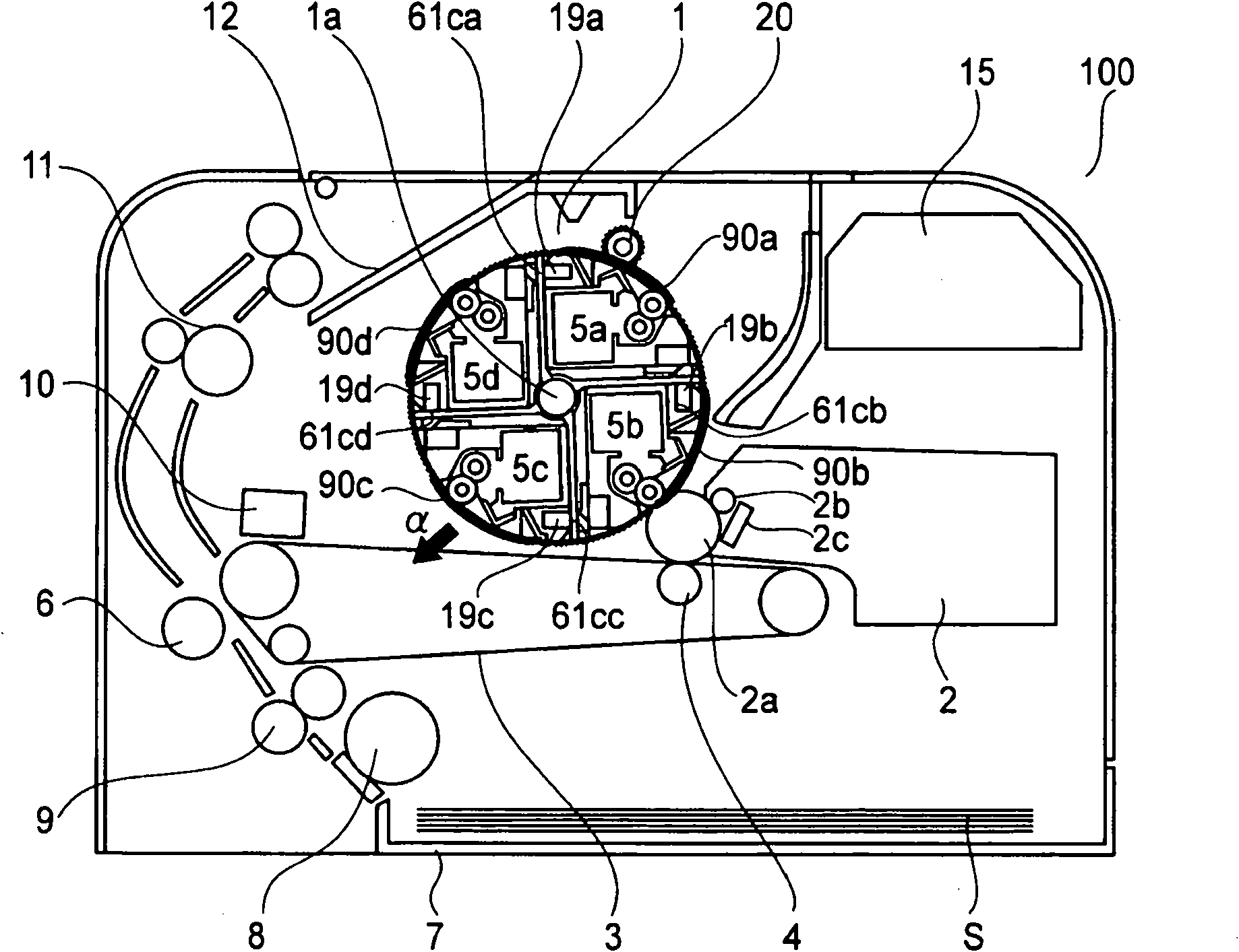
[0019] First, the structure of an image forming apparatus equipped with the developing cartridge according to this embodiment to form an image and its image forming operation will be described.
[0020] (General layout of color imaging equipment)
[0021] The image forming apparatus of this embodiment is a laser printer (four-color, full-color).
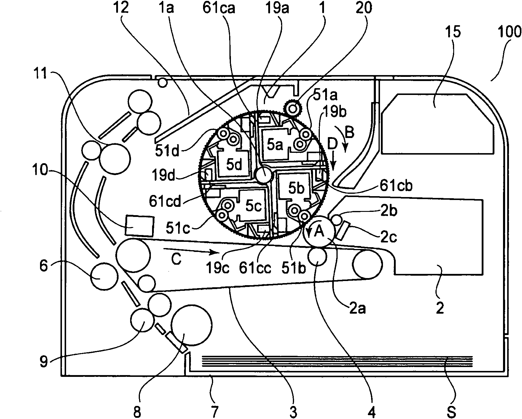
[0022] figure 2 It is a cross-sectional view showing a schematic structure during the developing operation of the yellow developing cartridge 5a.
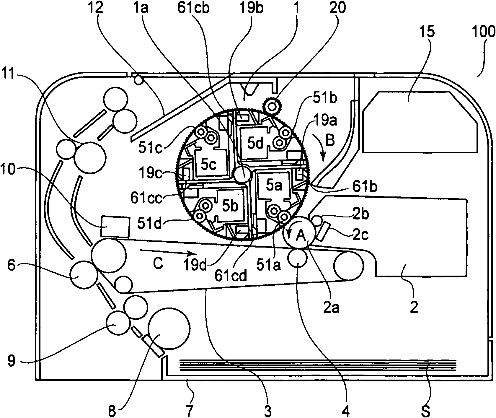
[0023] image 3 It is a cross-sectional view showing a schematic structure during the developing operation of the black developing cartridge 5d.
[0024] Such as figure 2 As shown, the image forming apparatus 100 includes a photosensitive drum 2a, which is an image bearing member, on which an electrostatic latent image will be formed. Around the photosensitive drum 2a, there is provided a charging device (charging roller 2b in this embodiment) for uniformly charging the photosensitive drum 2a, a...
no. 2 example
[0079] reference Figure 14 to 19 Described is a process cartridge and an electrophotographic image forming apparatus according to a second embodiment of the present invention.
[0080] Figure 14 An electrophotographic image forming apparatus (apparatus main assembly) 200 is shown, on which a plurality of process cartridges (cassettes) 250y, 250m, 250c, 250k are detachably mounted. These cartridges 250y, 250m, 250c, 250k contain yellow toner, magenta toner, cyan toner, and black toner (developer). Figure 15 Is a side sectional view of the box itself, Figure 16 It is a schematic diagram when the cartridge 250k is mounted on the main assembly of the device 200.
[0081] (General layout of electrophotographic imaging equipment)
[0082] Such as Figure 14 As shown, in the main assembly of the apparatus 200, the surfaces of the photosensitive drums 230y, 230m, 230c, and 230k are exposed with a laser beam 211 based on an image signal by means of a laser scanner 215. On each photosensi...
no. 3 example
[0112] (General layout of imaging equipment)
[0113] Picture 20 It is a perspective view of the external appearance of the imaging apparatus 100 according to this embodiment. Figure 21 It is a left sectional view of the imaging apparatus 100.
[0114] In the following description, the front side of the image forming apparatus 100 is the side where the recording material cassette 7 is loaded and unloaded. The back side is the side opposite to the front side. The forward and backward directions are the direction from the rear side to the front side (front direction) and the opposite direction (rear direction). Left and right are left or right when viewed from the front. The left direction and the right direction are the direction from right to left (left direction) and the opposite direction (right direction). One end of the electrophotographic photosensitive drum (image bearing member) in the longitudinal direction (axial direction) is the driving side, and the other end is th...
PUM
 Abstract
Description
Claims
Application Information
 - R&D
- Intellectual Property
- Life Sciences
- Materials
- Tech Scout
- Unparalleled Data Quality
- Higher Quality Content
- 60% Fewer Hallucinations
Browse by: Latest US Patents, China's latest patents, Technical Efficacy Thesaurus, Application Domain, Technology Topic, Popular Technical Reports.
© 2025 PatSnap. All rights reserved.Legal|Privacy policy|Modern Slavery Act Transparency Statement|Sitemap|About US| Contact US: help@patsnap.com


