Recoil-free ejecting device

A technology of recoil and rear piston, which is applied in the direction of weapon accessories, missile propellers, offensive equipment, etc. It can solve the problems of small mass, launch tube and bullet without electrical interface, etc., and achieve the effect of eliminating recoil

Active Publication Date: 2011-08-03
BEIJING MECHANICAL EQUIP INST
View PDF4 Cites 14 Cited by
  • Summary
  • Abstract
  • Description
  • Claims
  • Application Information

AI Technical Summary

Problems solved by technology

[0003] The purpose of the present invention is to provide a recoilless projectile device to solve the problem that the current projectile device can only launch shells with small mass and there is no electrical interface between the launch tube and the projectile

Method used


Image

  • Recoil-free ejecting device
  • Recoil-free ejecting device
  • Recoil-free ejecting device

Examples


Embodiment Construction

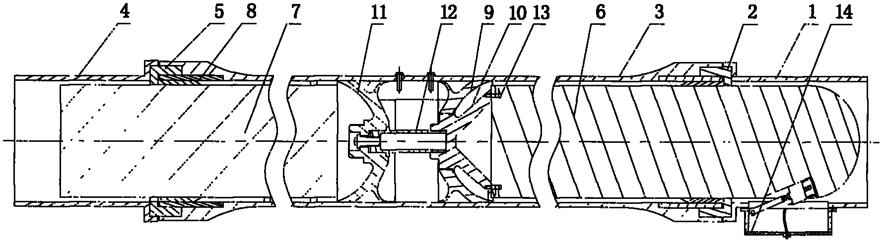
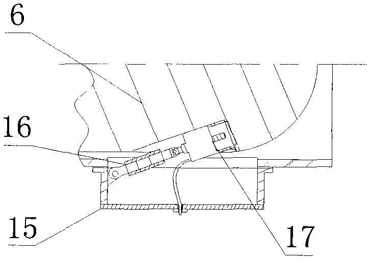
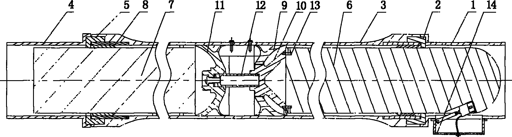
[0010] A recoilless projectile device, comprising: front cylinder body 1, front flange 2, middle cylinder body 3, rear cylinder body 4, rear flange 5, balance body 7, brake ring 8, front piston body 9, support seat 10. The rear piston 11, the ignition tube 12 and the lug 13 also include: a plug-in mechanism 14. Wherein, the plug-in mechanism 14 includes: a housing 15, an adjustable pull rod 16 and an electrical plug 17. One end of the support seat 10 is threadedly connected with the front piston body 9, and the other end is in the shape of a bell mouth. 13, one end is placed in the threaded hole, and the other end is screwed with the bullet 6. The rear piston 11 is threadedly connected with the balance body 7, the two ends of the middle cylinder 3 are threaded, the brake ring 8 is clamped with the two ends of the middle cylinder 3, the front flange 2 and the rear flange 5 are connected with the middle cylinder 3 Screwed and connected with brake ring 8 at the same time. One e...


PUM


Abstract

The invention discloses a recoil-free ejecting device, which comprises a front cylinder body (1), a front flange (2), a middle cylinder body (3), a rear cylinder body (4), a rear flange (5), a balance body (7), a brake ring (8), a front piston body (9), a support seat (10), a rear piston (11), an ignition tube (12) and a support lug (13), and also comprises a push-pull mechanism (14). The push-pull mechanism (14) comprises a shell, an adjustable pull rod and an electrical plug. One end of the adjustable pull rod is connected with a pin shaft of the shell, and the other end of the adjustable pull rod is connected with the pin shaft of the electrical plug; the shell is connected with the front cylinder body (1) by a bolt, and the electrical plug is obliquely inserted on a bomb (6) along an emission direction of the bomb (6). The fuel gas is closed in a hollow cavity between the two pistons (the front piston body (9), the middle cylinder body (3)) and the middle cylinder body (3) in the overall ejecting process, so micro sound, micro smoke and micro light are realized in the ejecting process and the recoil is eliminated.

Description

technical field [0001] The invention relates to a projectile device, in particular to a recoilless projectile device. Background technique [0002] Present projectile device generally comprises launching tube, front piston, rear piston, front flange, rear flange, ignition tube, balance body and braking ring. Shell, front piston, rear piston, ignition tube and balance body are all installed in the launch tube, the front piston is connected with the shell, the rear piston is connected with the balance body, the two pistons are connected through the ignition tube, and the brake rings are connected in the mouths of both ends of the barrel. Under the action of gas pressure, the ignition tube breaks into front and rear parts. The front and rear pistons respectively push the projectile and the balance body to move towards the two ends of the launch tube. When they reach the barrel mouth, they are braked by the front and rear brake rings, and the projectile and balance body are resp...

Claims


Application Information

Patent Timeline
Patent Type & Authority Applications(China)
IPC IPC(8): F41A1/08
CPCF41A1/10
Inventor 王生捷邱旭阳陈爱锋唐玉龙迟克刚
Owner BEIJING MECHANICAL EQUIP INST
Why Eureka
Try Eureka