

Method for development by utilizing UML (Unified Modeling Language) sequence diagram and activity diagram generation tool
A technology of sequence diagrams and activity diagrams, applied in program files, program control devices, software maintenance/management, etc., can solve problems such as difficulty in accurately expressing conditional branching and parallel event processing, and inability to express UML sequence diagrams.
- Summary
- Abstract
- Description
- Claims
- Application Information
AI Technical Summary
Problems solved by technology
Method used
Image

Examples
Embodiment 1
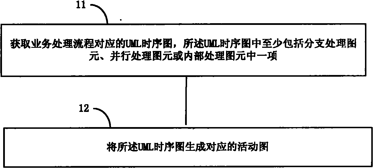
[0026] This embodiment provides a method for developing using UML sequence diagrams, such as figure 1 As shown, the following processing steps are included:
[0027] Step 11. Obtain the UML sequence diagram corresponding to the business processing flow, the UML sequence diagram includes at least one of branch processing primitives, parallel processing primitives or internal processing primitives;
[0028] Step 12, generating a corresponding activity diagram from the UML sequence diagram.
[0029] It can be seen from the technical solutions provided by the above-mentioned embodiments of the present invention that the embodiments of the present invention include at least one of branch processing primitives, parallel processing primitives, and internal processing primitives in the UML sequence diagram, and the The sequence diagram described above is converted into an activity diagram, so that different processing logics can be executed according to different situations of variou...
Embodiment 2
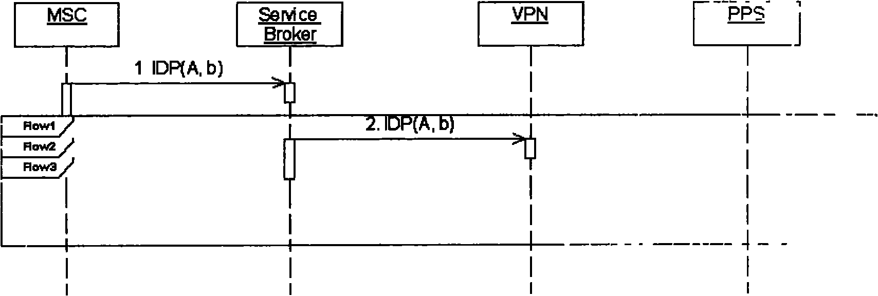
[0032] In this embodiment, there is a business processing flow with branch processing logic. When using the UML sequence diagram to represent the business processing flow with branch processing logic, it is necessary to set a plurality of branch primitives in the UML sequence diagram to represent multiple different Branch processing logic, such as Flow1 and Flow2, wherein the branch graphic element Flow1 corresponds to the first branch processing logic, and the branch graphic element Flow2 corresponds to the second branch processing logic. Therefore, when Flow1 or Flow2 is selected, the specific processing steps of the corresponding branch processing logic are displayed. What needs to be explained is: the representation method of the branch primitive, for example: figure 2 , use two side-by-side small square icons to represent three parallel branches. Of course, other shapes can also be set, such as setting a circle to represent branch primitives, and different colors can als...
Embodiment 3
[0046] During the processing of this embodiment, a certain network element needs to process multiple events at the same time, that is to say, there is a parallel processing logic in the processing process, so when the UML sequence diagram represents the process, it is necessary to set a Parallel processing of primitives, for example: such as Figure 4 As shown, the parallel processing graphic element can be represented by a black vertical small square, and the parallel processing graphic element takes effect after receiving the CON message returned by the VPN in step 4 and the RRBE message returned by the PPS in step 5. That is, Service Broker processes the above-mentioned CON message and RRBE message at the same time. If only one of the above-mentioned CON message and RRBE message is received, the above-mentioned parallel processing primitives will not take effect, that is, the Service Broker will not process the above-mentioned CON message or RRBE message, and the processing...
PUM
 Abstract
Description
Claims
Application Information