Connecting structure of evaporator and capillary tube

A connection structure and capillary technology, applied in the direction of fluid circulation arrangements, refrigeration components, refrigerators, etc., can solve problems such as capillary bending, inability to completely solve noise, complex processing technology, etc., to achieve small deformation, reduce probability, and reduce turbulence. flow effect

Active Publication Date: 2011-08-10
JIANGSU BAIXUE ELECTRIC APPLIANCES
View PDF5 Cites 12 Cited by
  • Summary
  • Abstract
  • Description
  • Claims
  • Application Information

AI Technical Summary

Problems solved by technology

The diameter of the connecting pipe in this patent is gradually enlarged, and the processing technology is relatively complicated; it can be seen from the attached drawings of the specification that there is a secondary throttling problem at the intersection of the structure, which has some impact on power consumption; in addition, the structure has no Considering the possibility that welding (high temperature) will cause the capillary to bend, it cannot completely solve the noise generated by the refrigerant impacting the wall of the evaporator tube due to phase change at the outlet end of the capillary

Method used


Image

  • Connecting structure of evaporator and capillary tube
  • Connecting structure of evaporator and capillary tube

Examples


Embodiment Construction

[0019] The technical scheme of the present invention will be further described below in conjunction with the embodiment shown in the accompanying drawings:

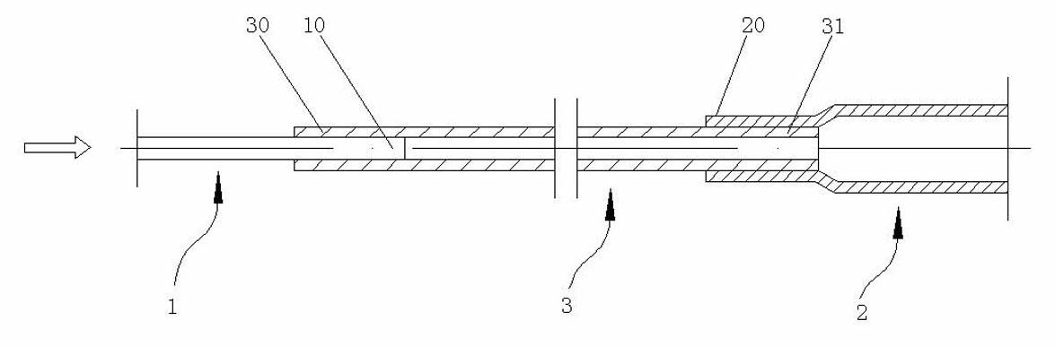
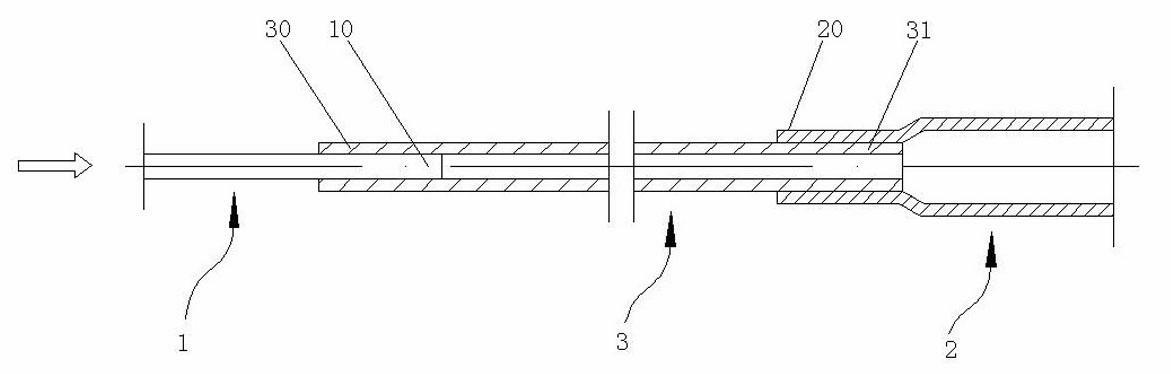
[0020] A connection structure between an evaporator and a capillary as shown in the figure, wherein: the capillary 1 has a liquid inlet and a liquid outlet 10, and the capillary 1 is made of pure copper (T2); the evaporator includes a liquid inlet 20 Evaporation tube 2.

[0021] Between the evaporating tube 2 and the capillary tube 1, a transition connecting pipe 3 is provided. The transition connecting pipe 3 is made of Bondi tube or pure copper (T2), and has a first connecting part 30 and a second connecting part 31. The transition connecting The tube inner diameter of the tube 3 at the first connecting part 30 is consistent with the tube outer diameter of the capillary tube 1 at the liquid outlet 30; the tube outer diameter of the transition connecting tube 3 at the second connecting part 31 is the same The inner diam...


PUM


Abstract

The invention relates to a connecting structure of an evaporator and a capillary tube, wherein the capillary tube is provided with a liquid inlet and a liquid outlet; the evaporator comprises an evaporation tube provided with a liquid inlet end; a transition connecting tube is arranged between the evaporation tube and the capillary tube; the transition connecting tube is provided with a first connecting part and a second connecting part; the internal diameter of the transition connecting tube at a first connecting part is consistent with the external diameter of the capillary tube at the liquid outlet; the external diameter of the transition connecting tube at a second connecting part is consistent with the internal diameter of the evaporation tube at the liquid inlet end; the first connecting part is connected with the liquid outlet of the capillary tube; the second connecting part is connected with the liquid inlet end; the internal diameters of the transition connecting tube at the first connecting part and the second connecting part are same; and the central lines of the capillary tube, the transition connecting tube and the evaporation tube are positioned on the same straight line. The connecting structure provided by the invention can effectively reduce the noise of a refrigerant in the flowing process by additionally arranging the transition connecting tube.

Description

technical field [0001] The invention relates to the field of mechanical engineering refrigeration or cooling, in particular to a connection structure between an evaporator and a capillary tube in a refrigeration cycle system in a refrigerator, a refrigerator, or a cooling or freezing device. Background technique [0002] Generally, a refrigerating device such as a refrigerator is equipped with a refrigerating cycle system, and cold air generated by the refrigerating cycle system is supplied to the inside of the refrigerating device to maintain a low temperature state. At present, the existing refrigeration cycle system includes: an evaporator that uses liquid refrigerant to generate cold air on the outside, a compressor that compresses the gaseous refrigerant flowing out of the evaporator, a condenser that condenses the compressed refrigerant, and makes the condensate It is composed of capillary tubes with low temperature of liquid refrigerant. The capillary converts the co...

Claims


Application Information

Patent Timeline
Patent Type & Authority Applications(China)
IPC IPC(8): F25B41/06
Inventor 张建标朱斌华顾清
Owner JIANGSU BAIXUE ELECTRIC APPLIANCES
Why Eureka
Try Eureka