Fluid valve

A fluid valve and fluid technology, applied in multi-way valves, valve devices, engine components, etc., can solve the problems of large amount of sealing rings, poor high-pressure fluid bearing capacity, poor sealing performance, etc., and achieves low requirements for fluid cleaning and reliable operation. The effect of long life, simple and reliable control

Inactive Publication Date: 2013-03-27
俞卫权
View PDF0 Cites 0 Cited by
  • Summary
  • Abstract
  • Description
  • Claims
  • Application Information

AI Technical Summary

Problems solved by technology

[0002] The traditional reciprocating reversing control uses too many trigger mechanisms similar to travel switches. The setting of multiple links is likely to cause reliability problems and complex structures. Usually, a cylindrical valve that moves along the axis to switch the control valve has to increase the structural characteristics of the valve. It is difficult to control the flow of fluid by using double spools or more spools in the same valve body. At the same time, using a cylindrical control valve that moves along the axis to switch, the high and low pressure areas are sealed only by simple valve sealing rings. The ability to withstand high-pressure fluid is poor. In addition, the entire valve uses a large amount of sealing rings. There are at least two sealing rings in any high-low pressure area. In this way, a single valve core must have a series of sealing components. If one of the sealing rings is damaged, it will affect Integral sealing, secondly, the above-mentioned gas or liquid control valve has quite high requirements on the cleanliness of the controlled gas or liquid medium, and even needs to add many series of auxiliary equipment for this purpose, which has high cost, poor sealing performance and directly affects the service life of the product and performance

Method used


Image

  • Fluid valve
  • Fluid valve
  • Fluid valve

Examples


Embodiment Construction

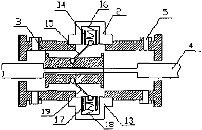
[0009] The present invention will be further described in detail below through specific embodiments in conjunction with the accompanying drawings.

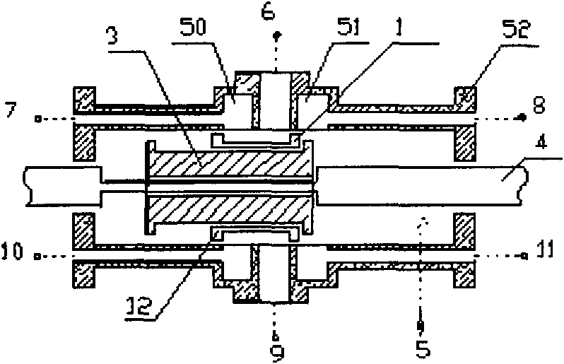
[0010] A fluid valve, comprising a valve body 52 and reversing valve cores 1 and 12 arranged in the inner cavity of the valve body 52, characterized in that the inner cavity of the valve body 52 communicates with the power fluid inlet 5, and the side wall of the valve body 52 is axially symmetrical At least two power fluid discharge ports 6, 9 are provided, and the two sides of each power fluid discharge port are respectively provided with a first communication port 50 and a second communication port 51, and one end of the valve body is provided with the first communication port 50 connected to the first control signal port 7,10, the other end of the valve body is provided with the second control signal port 8,11 connected with the second communication port 51, the valve body is provided with a reversing spool 1,12, the reversing ...


PUM


Abstract

The invention discloses a fluid valve which is characterized in that the inner cavity of a valve body is communicated with a dynamic fluid inlet; the side wall of the valve body is provided with at least two dynamic fluid leakage openings in an axial symmetrical mode; two sides of each dynamic fluid leakage opening are respectively provided with a first communicated opening and a second communicated opening; the valve body is provided with a first control signal opening connected with the first communicated opening and a second control signal opening connected with the second communicated opening; a reversing valve core comprises at least two top end seals and a hollow body with the open bottom part; the opening at the bottom part of the hollow body is arranged towards the dynamic fluid leakage opening and is in contact with slidingly with the seal plane of the inner wall of the valve body; the inner space of the hollow body is communicated with the dynamic fluid leakage openings; and the outer space of the hollow body is communicated with the dynamic fluid inlet. The fluid valve provided by the invention has the advantages of simple structure, reliability, low cost, high-pressure resistance, large flow rate, working reliability, long service life and wide scope of application.

Description

technical field [0001] The invention relates to a fluid valve, in particular to a fluid valve for controlling gas or liquid. Background technique [0002] The traditional reciprocating reversing control uses too many trigger mechanisms similar to travel switches. The setting of multiple links is likely to cause reliability problems and complex structures. Usually, a cylindrical valve that moves along the axis to switch the control valve has to increase the structural characteristics of the valve. It is difficult to control the flow of fluid by using double spools or more spools in the same valve body. At the same time, using a cylindrical control valve that moves along the axis to switch, the high and low pressure areas are sealed only by simple valve sealing rings. The ability to withstand high-pressure fluid is poor. In addition, the entire valve uses a large amount of sealing rings. There are at least two sealing rings in any high-low pressure area. In this way, a single ...

Claims


Application Information

Patent Timeline
Patent Type & Authority Patents(China)
IPC IPC(8): F16K11/065
Inventor 俞卫权
Owner 俞卫权
Why Eureka
Try Eureka