Fluid power machine

A power machine and fluid technology, applied in the direction of machines/engines, liquid variable capacity machines, mechanical equipment, etc., can solve the problems of affecting the overall seal, poor sealing performance, and large amount of sealing rings

Inactive Publication Date: 2013-04-17
俞卫权
View PDF6 Cites 0 Cited by
  • Summary
  • Abstract
  • Description
  • Claims
  • Application Information

AI Technical Summary

Problems solved by technology

[0002] Traditional reciprocating pumps, reciprocating compressors, fluid power machines, reciprocating equipment, etc. use the motor's rotational motion to convert it into the reciprocating motion of the crank-link mechanism. The uninterrupted speed change during this motion will greatly damage the moving parts, and the cylinder is affected by the reciprocating motion. The side thrust is large and the work is rough, especially the manufacturing requirements of the crankshaft are high, the cost is high, and the size is limited. Reliability issues and complex structure, the fluid reversing control valve usually uses a cylindrical control valve that moves along the axis to switch, and its valve structure features To increase the control fluid flow, double spools or more spools are arranged in the same valve body. It is difficult to realize, and the control valve that uses cylindrical movement and switching along the axis at the same time, the high and low pressure areas are sealed only by simple valve sealing rings, which has poor bearing capacity for high-pressure fluids. In addition, the entire valve uses a large amount of sealing rings. There are at least two sealing rings in the low-pressure area. In this order, a single valve core must have a series of sealing components. If one of the sealing rings is damaged, the overall sealing will be affected. Secondly, the above-mentioned gas or liquid control valve is suitable for the controlled gas or liquid medium. There are quite high requirements for cleanliness, and many series of auxiliary equipment are even added for this purpose, which has high cost and poor sealing performance, and directly affects the service life and performance of the product

Method used


Image

  • Fluid power machine
  • Fluid power machine
  • Fluid power machine

Examples


Embodiment Construction

[0009] The present invention will be further described in detail below through specific embodiments in conjunction with the accompanying drawings.

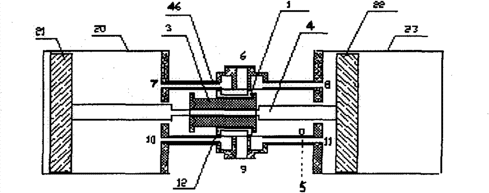
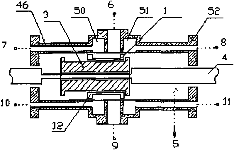
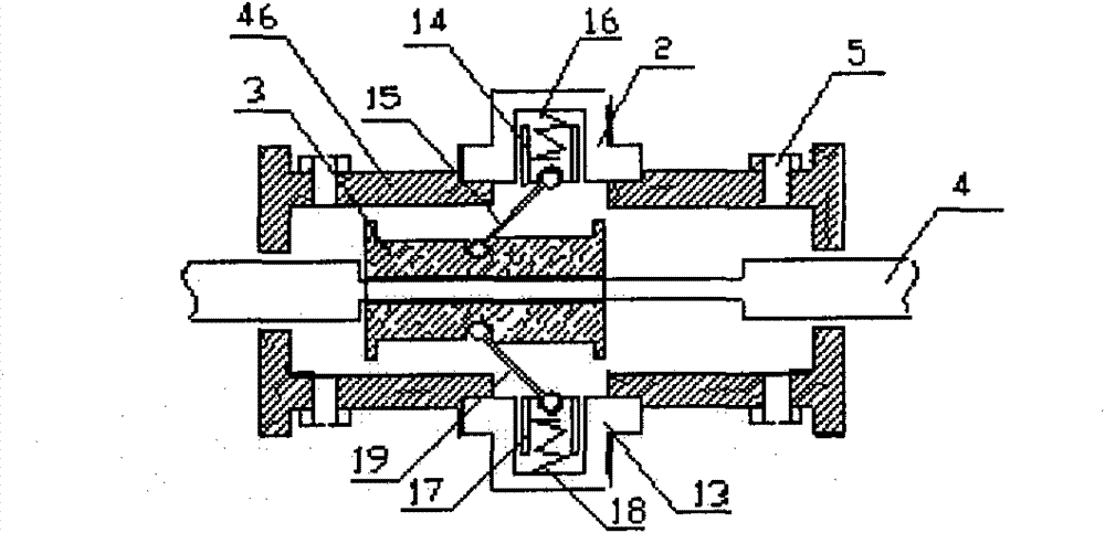
[0010] A kind of fluid power machine, comprises cylindrical cylinder body 20,23, piston 21,22, reversing fluid valve 46, it is characterized in that: the two ends of reversing fluid valve 46 are respectively provided with a cylindrical cylinder body 20,23, each A piston 21, 22 is arranged inside the cylindrical cylinder body 20, 23, the inner side of the piston 21, 22 is a piston drive chamber, the two pistons are connected by a piston rod 4, and the reversing fluid valve 46 is provided with a power fluid inlet 5 and outlets 6, 9, one end of the reversing fluid valve 46 is provided with the first control port 7, 10 communicated with the piston drive chamber on this side, and the other end of the reversing fluid valve 46 is provided with the second control port communicated with the piston drive chamber on the other side. The contr...


PUM


Abstract

The invention discloses a fluid power machine which is characterized in that at least one end of a reversing fluid valve is provided with a barrel-type cylinder body; each barrel-type cylinder body is provided with a piston internally; each piston is connected with a piston rod; each barrel-type cylinder body of the reversing fluid valve is provided with a first piston driving chamber and a second piston driving chamber internally; the reversing fluid valve is provided with a dynamic fluid inlet and a dynamic fluid outlet, and also provided with a first control opening and a second control opening which are communicated with the first piston driving chamber and the second piston driving chamber; the piston rod is provided with a touch slide block; and the touch slide block is matched witha reversing valve plug which is arranged in the inner cavity of the fluid body of the reversing fluid valve. The fluid power machine provided by the invention has the advantages of simple structure, reliability, low cost, strong functions, long reliable working service life and wide application range.

Description

technical field [0001] The invention relates to a fluid power machine, in particular to a fluid power machine powered by gas or liquid. Background technique [0002] Traditional reciprocating pumps, reciprocating compressors, fluid power machines, reciprocating equipment, etc. use the motor's rotational motion to convert it into the reciprocating motion of the crank-link mechanism. The uninterrupted speed change during this motion will greatly damage the moving parts, and the cylinder is affected by the reciprocating motion. The side thrust is large and the work is rough, especially the manufacturing requirements of the crankshaft are high, the cost is high, and the size is limited. Reliability issues and complex structure, the fluid reversing control valve usually uses a cylindrical control valve that moves along the axis to switch, and its valve structure features To increase the control fluid flow, double spools or more spools are arranged in the same valve body. It is d...

Claims


Application Information

Patent Timeline
Patent Type & Authority Patents(China)
IPC IPC(8): F04B5/00F04B49/22
Inventor 俞卫权
Owner 俞卫权
Why Eureka
Try Eureka