Fluid pressurizing machine

A supercharger and fluid technology, applied in the direction of liquid variable volume machinery, mechanical equipment, machines/engines, etc., can solve the problems of a large number of sealing rings, poor high-pressure fluid bearing capacity, poor sealing performance, etc., and meet the fluid cleaning requirements. Low, simple and reliable control, the effect of simple function structure

Inactive Publication Date: 2014-08-20
俞卫权
View PDF4 Cites 0 Cited by
  • Summary
  • Abstract
  • Description
  • Claims
  • Application Information

AI Technical Summary

Problems solved by technology

[0002] Traditional fluid pressurization uses purely mechanical push-push plunger method or single-stage pressurization uses two different piston areas similar to the Pascal principle of a jack. The pressurization is limited by the single-stage compression ratio to produce a high-pressure or ultra-high-pressure fluid pressurization. It is difficult to achieve. Other reciprocating booster reversing controls use a trigger mechanism similar to a travel switch. The setting of multiple links is likely to cause reliability problems and complex structures. Traditional fluid reversing control valves usually use cylindrical movement along the axis to switch It is difficult to realize the structural characteristics of the control valve by using double spools or more spools in the same valve body to increase the control fluid flow rate. At the same time, it is difficult to use a cylindrical control valve that moves along the axis to switch between high and low pressure. Zone sealing only relies on simple valve sealing rings, which has poor bearing capacity for high-pressure fluids. In addition, the entire valve uses a large amount of sealing rings. There are at least two sealing rings in any high-low pressure zone. In this order, a single valve core must have a series of sealing rings. If one of the sealing rings is damaged, it will affect the overall sealing. Secondly, the above-mentioned gas or liquid control valves have very high requirements on the cleanliness of the controlled gas or liquid medium, and even many series of auxiliary equipment need to be added for this purpose. High cost, poor sealing performance, and directly affect product life and performance

Method used


Image

  • Fluid pressurizing machine
  • Fluid pressurizing machine
  • Fluid pressurizing machine

Examples


Embodiment Construction

[0010] The present invention will be further described in detail below through specific embodiments in conjunction with the accompanying drawings.

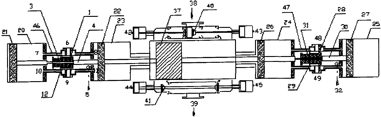
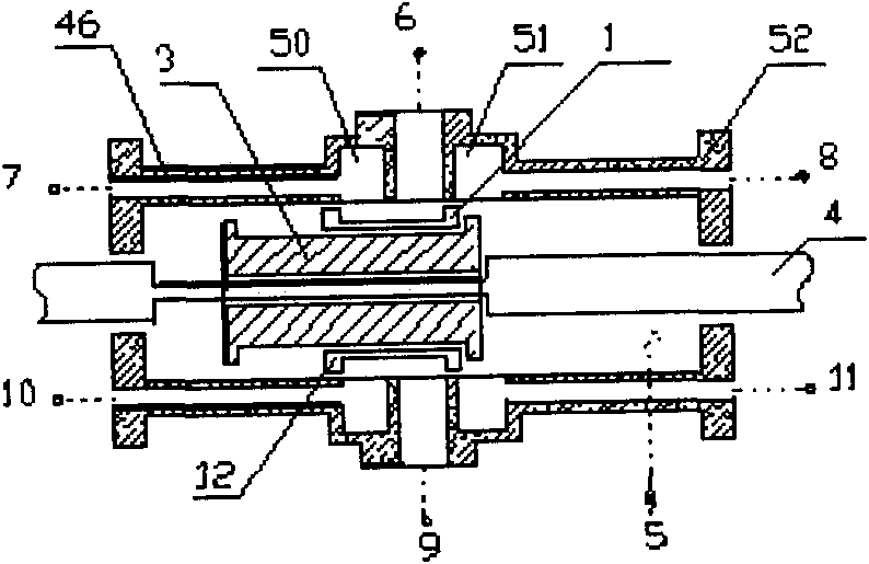
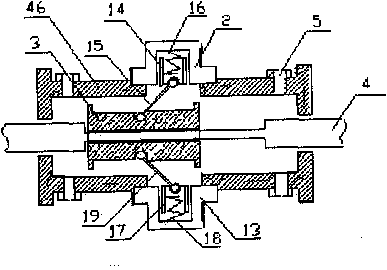
[0011] figure 1 A kind of fluid supercharging machine, comprises cylindrical cylinder 20, 23, 24, 25, piston 21, 22, 26, 27, reversing fluid valve 46, 47, is characterized in that: described reversing fluid valve is at least Two, at least one end of each reversing fluid valve is provided with a cylindrical cylinder, each cylindrical cylinder is provided with a piston and a drive chamber, the piston in the cylindrical cylinder is connected by a piston rod, and the reversing fluid valve Power fluid inlets 5, 32 and power fluid outlets 6, 9, 48, 49 are provided. The reversing fluid valve is also provided with a control signal port connected to the power fluid inlet or power fluid outlet. The drive cavity is connected. The working plunger 37 of the actuator is connected to the piston rod, and the cavities on both sides of the workin...


PUM


Abstract

The invention discloses a fluid pressurizing machine, which comprises barrel-type cylinder bodies, pistons and at least two reversing fluid valves and is characterized in that: at least one end of each reversing fluid valve is provided with the barrel-type cylinder bodies; each barrel-type cylinder body is provided with a piston and an actuating chamber; the pistons in the barrel-type cylinder bodies are connected with one another through piston rods; each reversing fluid valve is provided with a power fluid inlet and a power fluid outlet and is also provided with a control signal port which is connected with the power fluid inlet or the power fluid outlet; and control signal ports are communicated with the actuating chambers of the barrel-type cylinder bodies. The machine has the advantages of realizing the same function, along with simple structure, low cost, strong function, reliability of operation and long service life.

Description

technical field [0001] The invention relates to a fluid booster, in particular to a fluid booster which is powered by gas or liquid and is suitable for high pressure or super high pressure. Background technique [0002] Traditional fluid pressurization uses purely mechanical push-push plunger method or single-stage pressurization uses two different piston areas similar to the Pascal principle of a jack. The pressurization is limited by the single-stage compression ratio to produce a high-pressure or ultra-high-pressure fluid pressurization. It is difficult to achieve. Other reciprocating booster reversing controls use a trigger mechanism similar to a travel switch. The setting of multiple links is likely to cause reliability problems and complex structures. Traditional fluid reversing control valves usually use cylindrical movement along the axis to switch It is difficult to realize the structural characteristics of the control valve by using double spools or more spools in ...

Claims


Application Information

Patent Timeline
Patent Type & Authority Patents(China)
IPC IPC(8): F04B5/00F04B49/22
Inventor 俞卫权
Owner 俞卫权
Why Eureka
Try Eureka