LED drive circuit, dimming device, LED illumination fixture, LED illumination device, and LED illumination system

a technology of led drive circuit and dimming device, which is applied in the direction of lighting and heating apparatus, process and machine control, instruments, etc., can solve the problems of unavoidable small variations in flickering or blinking is known to occur, and the current value of the led module is not known to be small, so as to reduce the flickering effect of the led

Inactive Publication Date: 2013-03-19
SHARP KK
View PDF32 Cites 50 Cited by
  • Summary
  • Abstract
  • Description
  • Claims
  • Application Information

AI Technical Summary

Benefits of technology

[0017]An object of the present invention is to provide an LED drive circuit, a phase control dimming device, an LED illumination fixture, an LED illumination device, and an LED illumination system capable of reducing LED flicker during low-luminance dimming.
[0037]Through the present invention, since a switching element connected in series to an LED is pulse-driven during low-luminance dimming, the LED can be prevented from being controlled at an operating point that is susceptible to noise, such as operating point C in FIG. 2B and FIG. 20. It is therefore possible to reduce flickering of the LED during low-luminance dimming.

Problems solved by technology

However, when the incandescent bulb 41 is dimmed by the phase control dimmer 2 as shown in FIG. 16, flickering or blinking is known to occur, and normal dimming is not possible when a low-wattage incandescent bulb is used as the incandescent bulb 41.
However, small variations in the current value of the LED module 3 are unavoidable due to the temperature characteristics of such components as the LED module 3, the switching power supply unit for feeding current to the LED module 3, the phase control dimmer 2, and the alternating voltage outputted from the alternating-current power supply 1, and switch noise of the triac Tri1 of the phase control dimmer 2, switching noise of the switching power supply unit for feeding current to the LED module 3, and other noise.

Method used


Image

  • LED drive circuit, dimming device, LED illumination fixture, LED illumination device, and LED illumination system
  • LED drive circuit, dimming device, LED illumination fixture, LED illumination device, and LED illumination system
  • LED drive circuit, dimming device, LED illumination fixture, LED illumination device, and LED illumination system

Examples


first embodiment

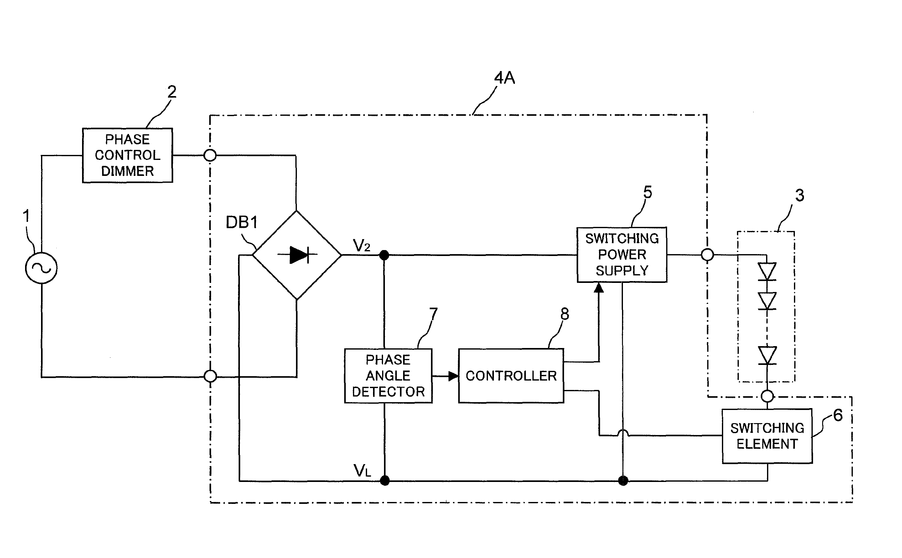
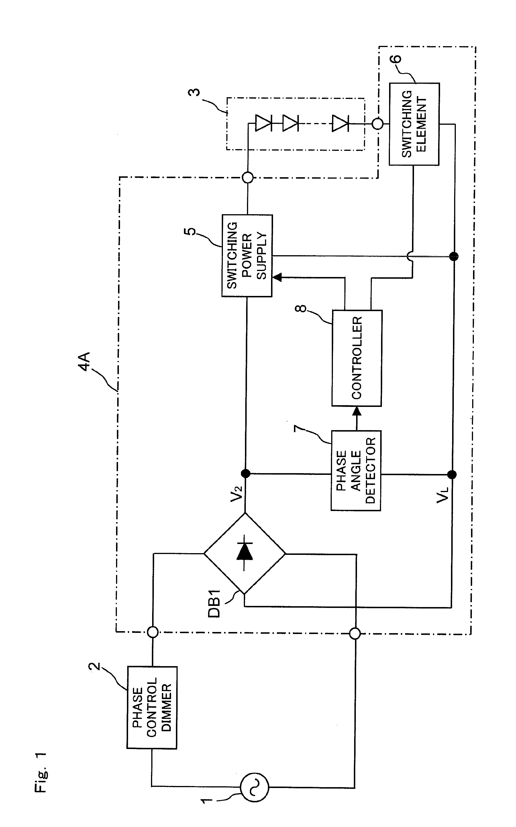
[0066]FIG. 1 shows the configuration of the LED illumination system according to a first embodiment of the present invention. The same reference symbols are used in FIG. 1 to refer to components that are the same as those in FIG. 18, and no detailed description thereof will be given. The LED illumination system according to the first embodiment of the present invention shown in FIG. 1 is provided with a phase control dimmer 2, an LED module 3, and an LED drive circuit 4A. The LED drive circuit 4A is an example of the LED drive circuit according to the present invention, and has a diode bridge DB1, a switching power supply 5, a switching element 6, a phase angle detector 7 for detecting the phase angle when the output voltage (V2−VL) of the diode bridge DB1 rapidly rises, and a controller 8 for controlling the switching power supply 5 and the switching element 6 in accordance with the phase angle detected by the phase angle detector 7. In the LED illumination system according to the ...

second embodiment

[0072]FIG. 4 shows the configuration of the LED illumination system according to a second embodiment of the present invention. The same reference symbols are used in FIG. 4 to refer to components that are the same as those in FIG. 1, and no detailed description thereof will be given.

[0073]In the configuration of the LED illumination system according to the second embodiment of the present invention shown in FIG. 4, the LED drive circuit 4A of the LED illumination system according to the first embodiment of the present invention shown in FIG. 1 is substituted with an LED drive circuit 4B.

[0074]The LED drive circuit 4B has the configuration of the LED drive circuit 4A with the addition of a current detector 9 for detecting the current of the LED module 3. In the LED drive circuit 4B, a step-up switching power supply circuit having a switching element 10 is used as the switching power supply 5, the switching element 6 is composed of an N-channel MOS transistor, the phase angle detector...


PUM


Abstract

An LED drive circuit in which an alternating voltage from a phase control dimmer is input and an LED is driven. The LED drive circuit comprises a phase angle detector for detecting the phase angle at which a phase control element inside the phase control dimmer switches from off to on; a switching power supply for feeding a current to the LED; a switching element connected in series to the LED; and a controller for controlling the switching power supply and the switching element in accordance with the output of the phase angle detector; wherein the controller places the switching element in an always-on state in a case in which the phase angle detected by the phase angle detector is equal to or less than a predetermined value, and the controller pulse-drives the switching element in a case in which the phase angle detected by the phase angle detector is greater than the predetermined value.

Description

[0001]This nonprovisional application claims priority under 35 U.S.C. §119(a) on Patent Application No. 2010-024376 filed in Japan on Feb. 5, 2010, the entire contents of which are hereby incorporated by reference.BACKGROUND OF THE INVENTION[0002]1. Field of the Invention[0003]The present invention relates to an LED drive circuit for driving an LED (light emitting diode), to a dimming device for dimming an LED, and to an LED illumination fixture, an LED illumination device, and an LED illumination system having an LED as a light source.[0004]2. Description of Related Art[0005]LEDs have such characteristics as low current consumption and long service life, and LED applications are expanding not only to display devices but to illumination fixtures and the like. In LED illumination fixtures, a plurality of LED units is often used in order to obtain the desired lighting intensity.[0006]Common illumination fixtures usually use a commercial AC 100 V power supply, and in cases in which an ...

Claims


Application Information

Patent Timeline
Patent Type & Authority Patents(United States)
IPC IPC(8): G05F1/00
CPCH05B33/0809Y02B20/348H05B45/375H05B45/38H05B45/385Y02B20/30F21Y2115/10
Inventor KANAMORI, ATSUSHIWARITA, HIROHISA
Owner SHARP KK
Why Eureka
Try Eureka