

LED drive circuit, LED illumination fixture, LED illumination device, and LED illumination system
a technology of led drive circuit and led illumination fixture, which is applied in the direction of lighting and heating apparatus, process and machine control, instruments, etc., can solve the problems of flickering or blinking, and the inability to achieve normal dimming, and achieve the effect of flickering of led
- Summary
- Abstract
- Description
- Claims
- Application Information
AI Technical Summary
Benefits of technology
Problems solved by technology
Method used
Image

Examples
first embodiment
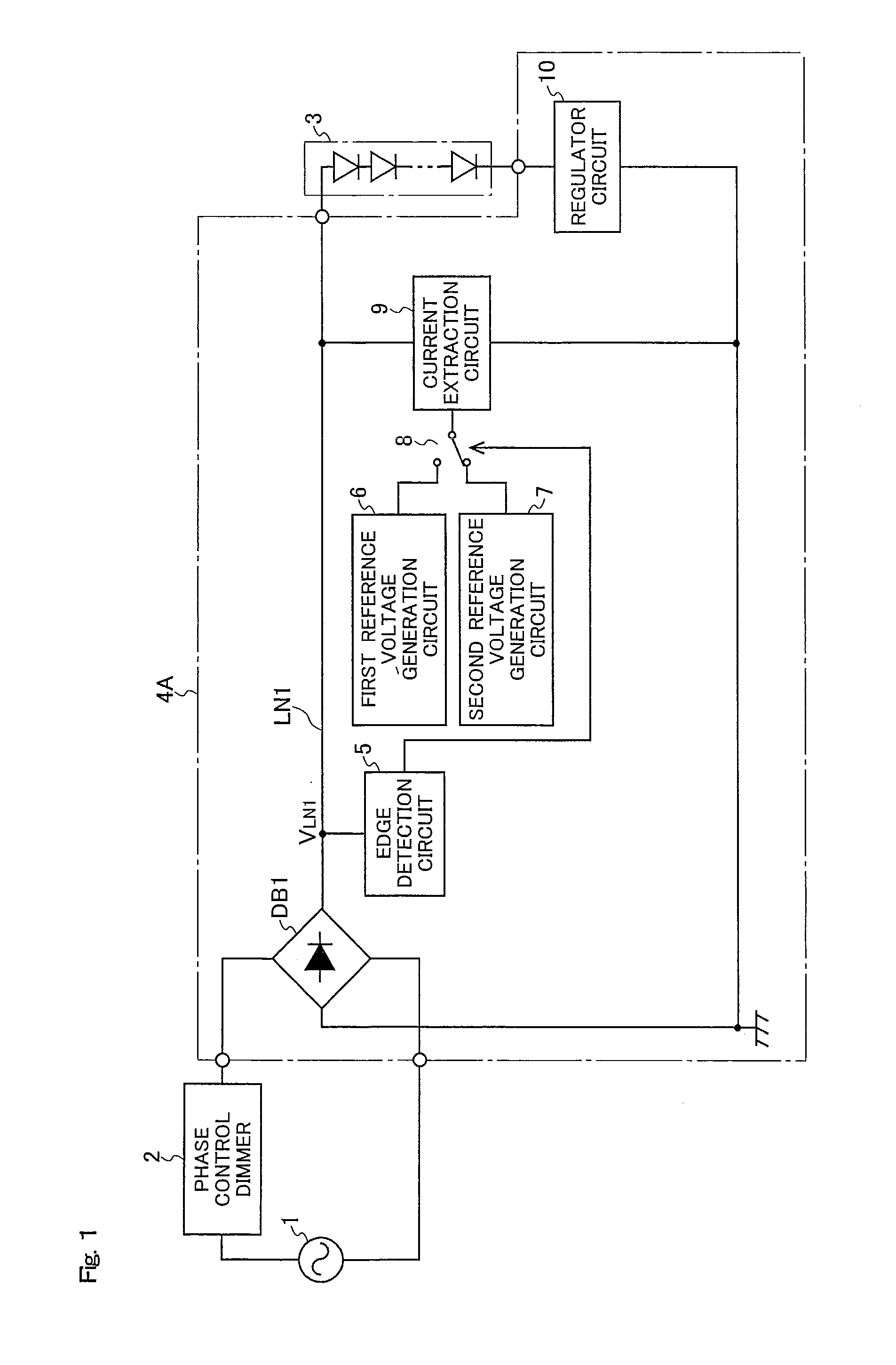
[0075]FIG. 1 shows the configuration of the LED illumination system according to a first embodiment of the present invention. The same reference symbols are used in FIG. 1 to refer to components that are the same as those in FIG. 20, and no detailed description thereof will be given. The LED illumination system according to the first embodiment of the present invention shown in FIG. 1 is provided with a phase control dimmer 2, an LED module 3, and an LED drive circuit 4A. The LED drive circuit 4A is an example of the LED drive circuit according to the present invention, and has a diode bridge DB1, an edge detection circuit 5, a first reference voltage generation circuit 6, a second reference voltage generation circuit 7, a switch 8, a current extraction circuit 9, and a regulator circuit 10.
[0076]In the LED illumination system according to the first embodiment of the present invention shown in FIG. 1, an alternating-current power supply 1 and the phase control dimmer 2 are connected...
second embodiment
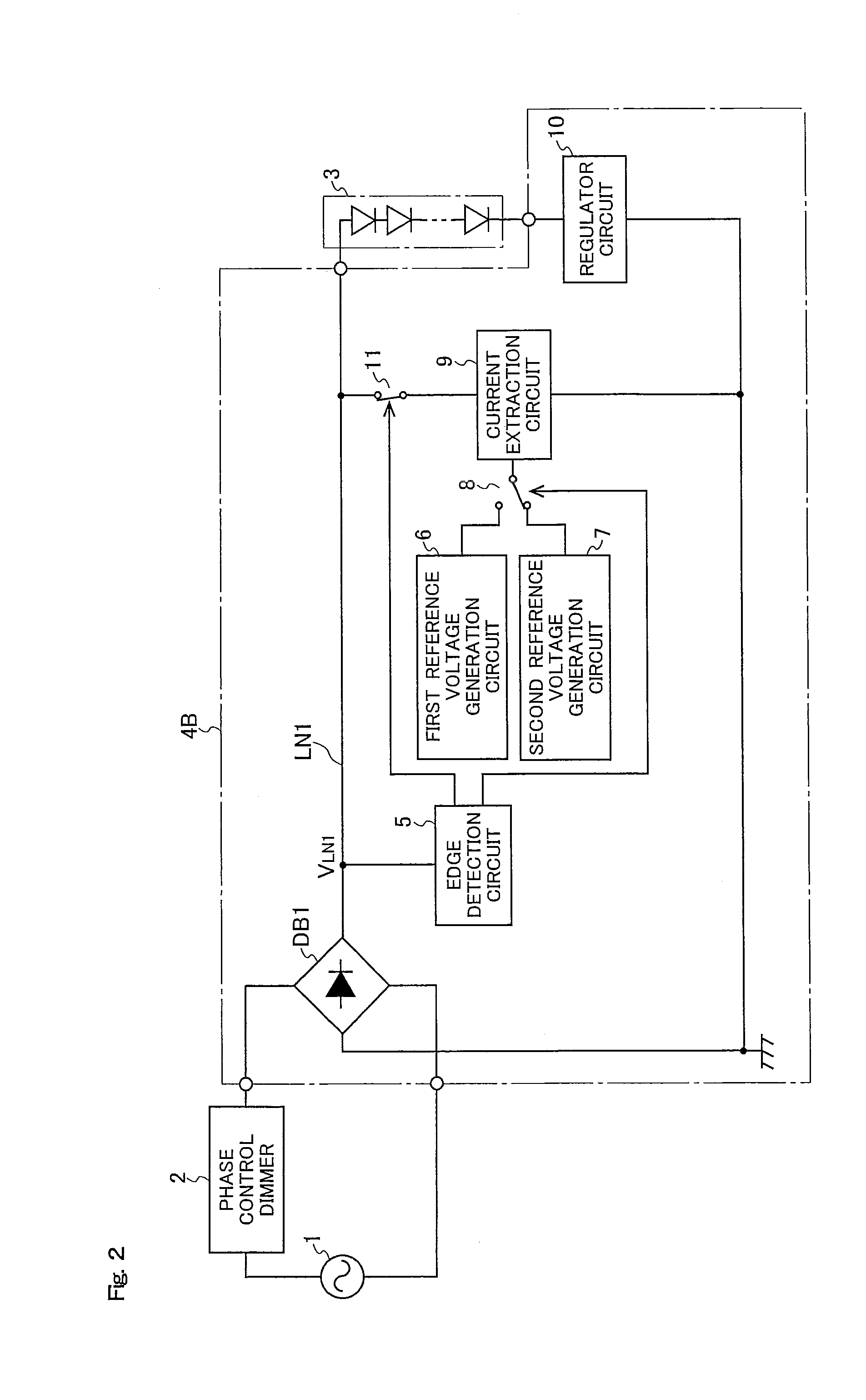
[0086]FIG. 2 shows the configuration of the LED illumination system according to a second embodiment of the present invention. The same reference symbols are used in FIG. 2 to refer to components that are the same as those in FIG. 1, and no detailed description thereof will be given. The LED illumination system according to the second embodiment of the present invention shown in FIG. 2 is provided with a phase control dimmer 2, an LED module 3, and an LED drive circuit 4B. The LED drive circuit 4B is an example of the LED drive circuit according to the present invention, and has the configuration of the LED drive circuit 4A described above with the addition of a switch 11.
[0087]The switch 11 is provided between the power supply feed line LN1 and the current extraction circuit 9. In a case in which the edge detection circuit 5 does not detect an edge in the voltage VLN1 for a certain period of time (e.g., half a cycle of the output voltage of the alternating-current power supply 1), ...
third embodiment
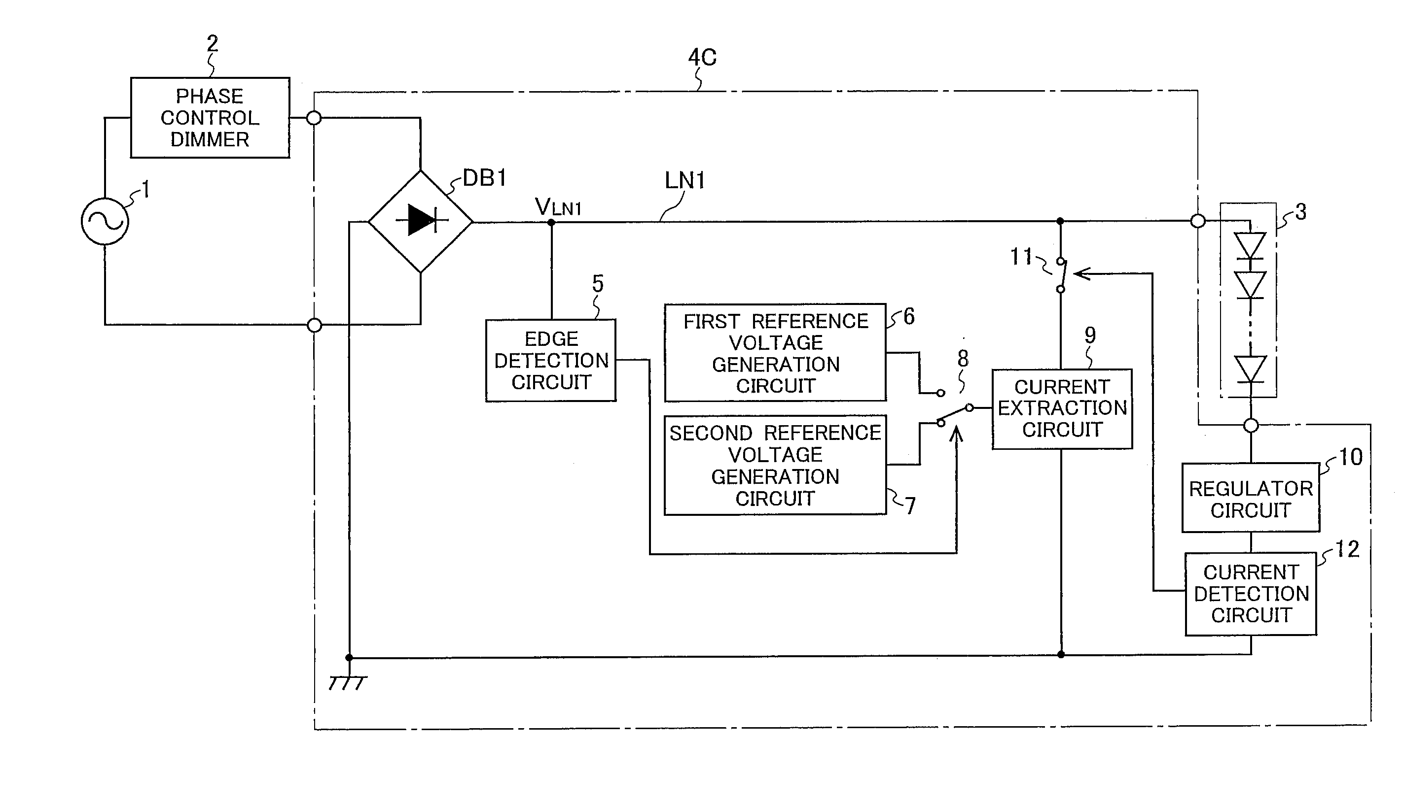
[0089]FIG. 3 shows the configuration of the LED illumination system according to a third embodiment of the present invention. The same reference symbols are used in FIG. 3 to refer to components that are the same as those in FIG. 2, and no detailed description thereof will be given. The LED illumination system according to the third embodiment of the present invention shown in FIG. 3 is provided with a phase control dimmer 2, an LED module 3, and an LED drive circuit 4C. The LED drive circuit 4C is an example of the LED drive circuit according to the present invention, and has the configuration of the LED drive circuit 4B described above with the addition of a current detection circuit 12.
[0090]The current detection circuit 12 detects the LED drive current flowing to the LED module 3. The switch 11 operates in accordance with the detection results of the current detection circuit 12, rather than the detection results of the edge detection circuit 5. From the perspective of the phase...
PUM
 Abstract
Description
Claims
Application Information