LED drive circuit, phase control dimmer, LED illumination fixture, LED illumination device, and LED illumination system

a technology of led drive circuit and phase control dimmer, which is applied in the direction of electric variable regulation, process and machine control, instruments, etc., can solve the problem of not being able to achieve normal dimming, and achieve the effect of reducing led flicker

Inactive Publication Date: 2011-06-30
SHARP KK
View PDF12 Cites 26 Cited by
  • Summary
  • Abstract
  • Description
  • Claims
  • Application Information

AI Technical Summary

Benefits of technology

[0020]An object of the present invention is to provide an LED drive circuit, a phase control dimmer, an LED illumination fixture, an LED illumination device, and an LED illumination system which are capable of reducing LED flicker during low-level dimming.
[0033]The LED illumination fixture according to the present invention for achieving the abovementioned objects may comprise an LED; and an LED flicker reduction unit for reducing flickering of the LED due to switching off of a phase control element inside the phase control dimmer before an alternating voltage inputted to the phase control dimmer reaches 0 V after the phase control element inside the phase control dimmer switches on and the LED emits light.
[0037]Through the present invention, a state such as the one shown in FIG. 22C does not occur, and flickering during low-level dimming can therefore be reduced.

Problems solved by technology

However, in cases in which an incandescent bulb is dimmed by a phase control dimmer, flickering or blinking is known to occur, and normal dimming is not possible when a low-wattage incandescent bulb is connected to the dimmer.

Method used


Image

  • LED drive circuit, phase control dimmer, LED illumination fixture, LED illumination device, and LED illumination system
  • LED drive circuit, phase control dimmer, LED illumination fixture, LED illumination device, and LED illumination system
  • LED drive circuit, phase control dimmer, LED illumination fixture, LED illumination device, and LED illumination system

Examples


first embodiment

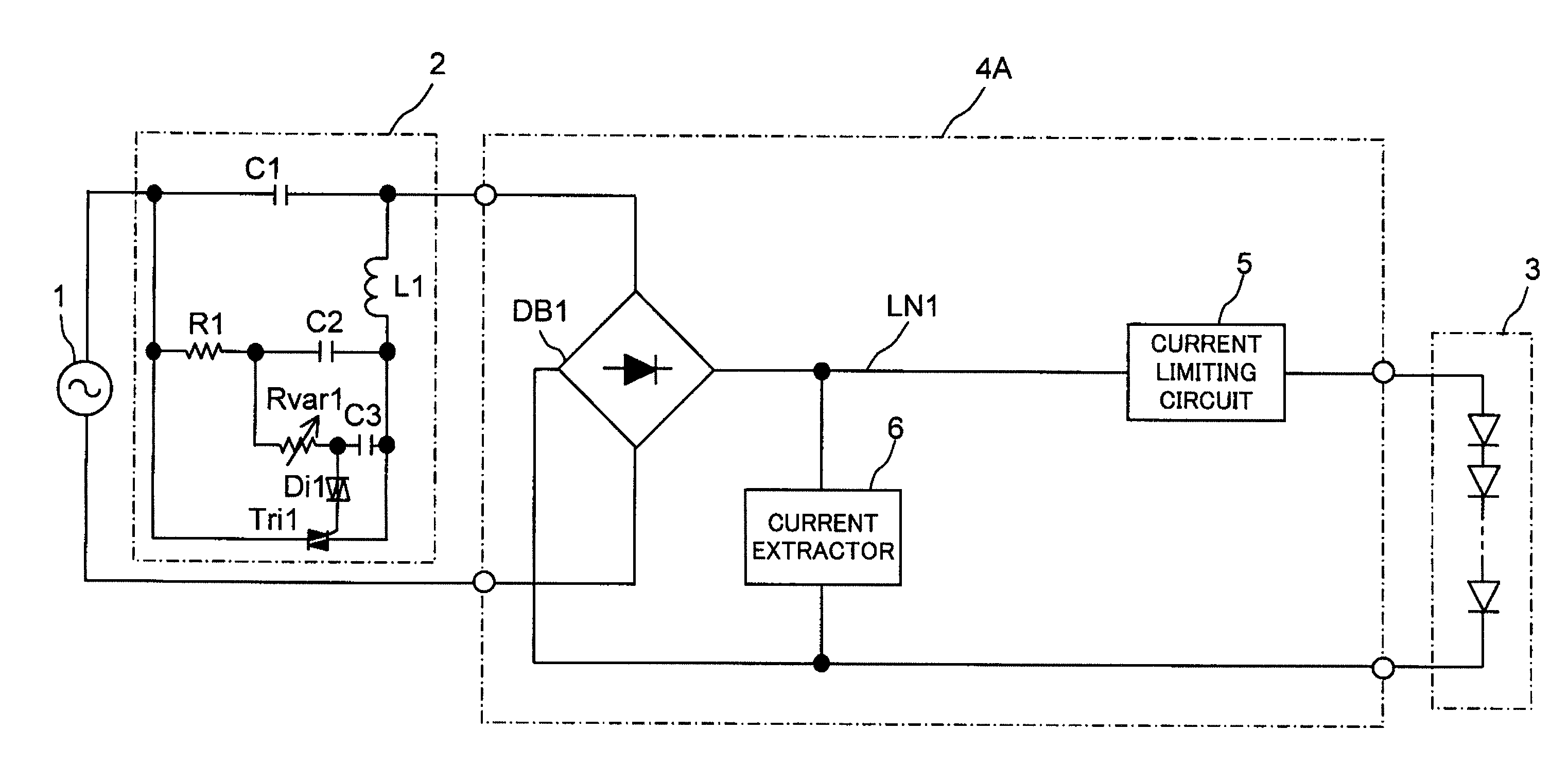
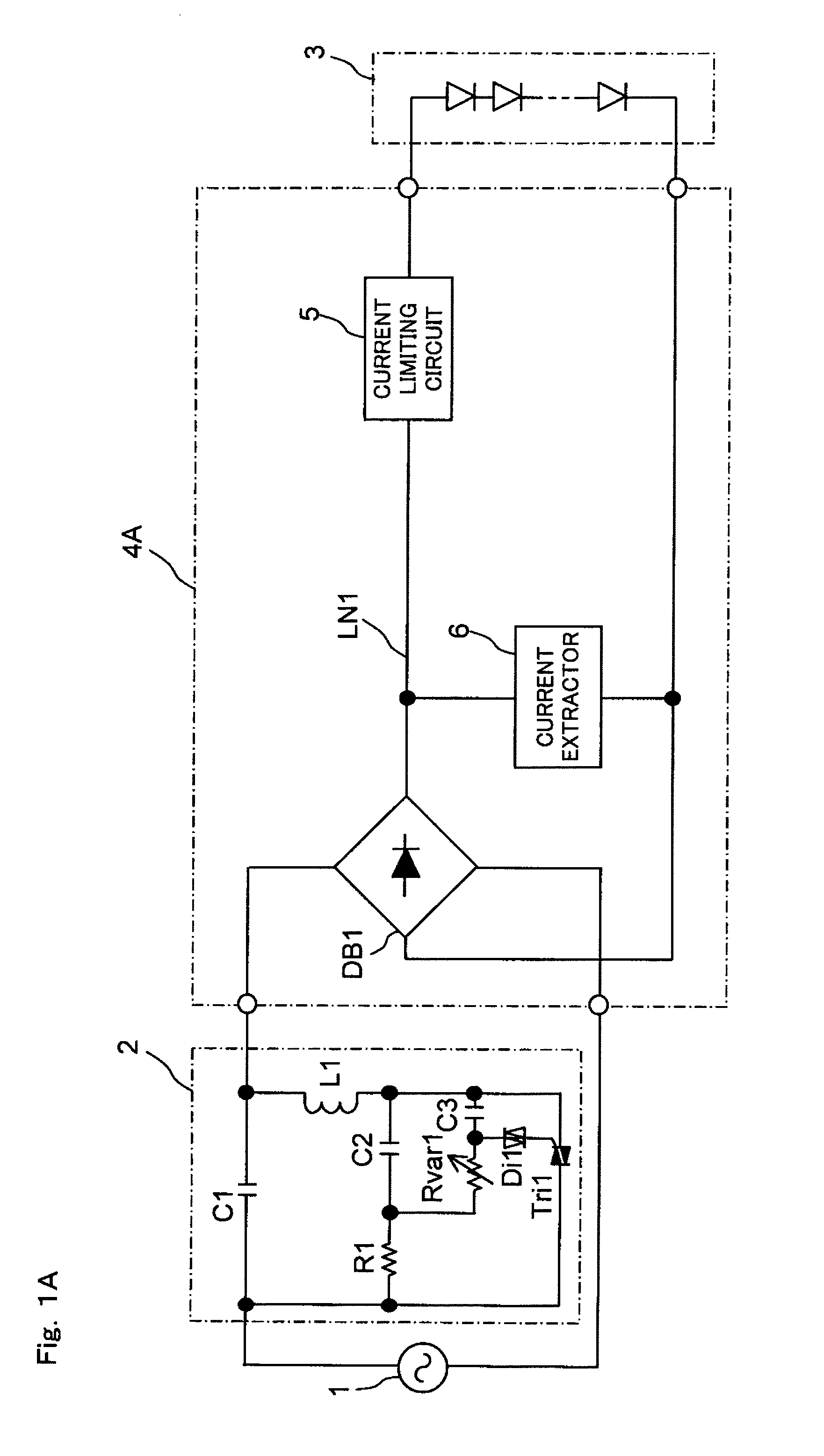
[0068]FIG. 1A shows the configuration of the LED illumination system according to a first embodiment of the present invention. The same reference symbols are used in FIG. 1A to refer to components that are the same as those in FIG. 17, and no detailed description thereof will be given. The LED illumination system according to the first embodiment of the present invention shown in FIG. 1A is provided with a phase control dimmer 2, an LED module 3, and an LED drive circuit 4A. The LED drive circuit 4A is an example of the LED drive circuit according to the present invention and is a direct-type (non-switching type) LED drive circuit, and has a diode bridge DB1, a current limiting circuit 5, and a current extractor 6. The current extractor 6 is provided between the output terminals of the diode bridge DB1, and extracts a current from a power supply feed line LN1 for feeding an LED drive current to the LED module 3 during operation. In the LED illumination system according to the first ...

second embodiment

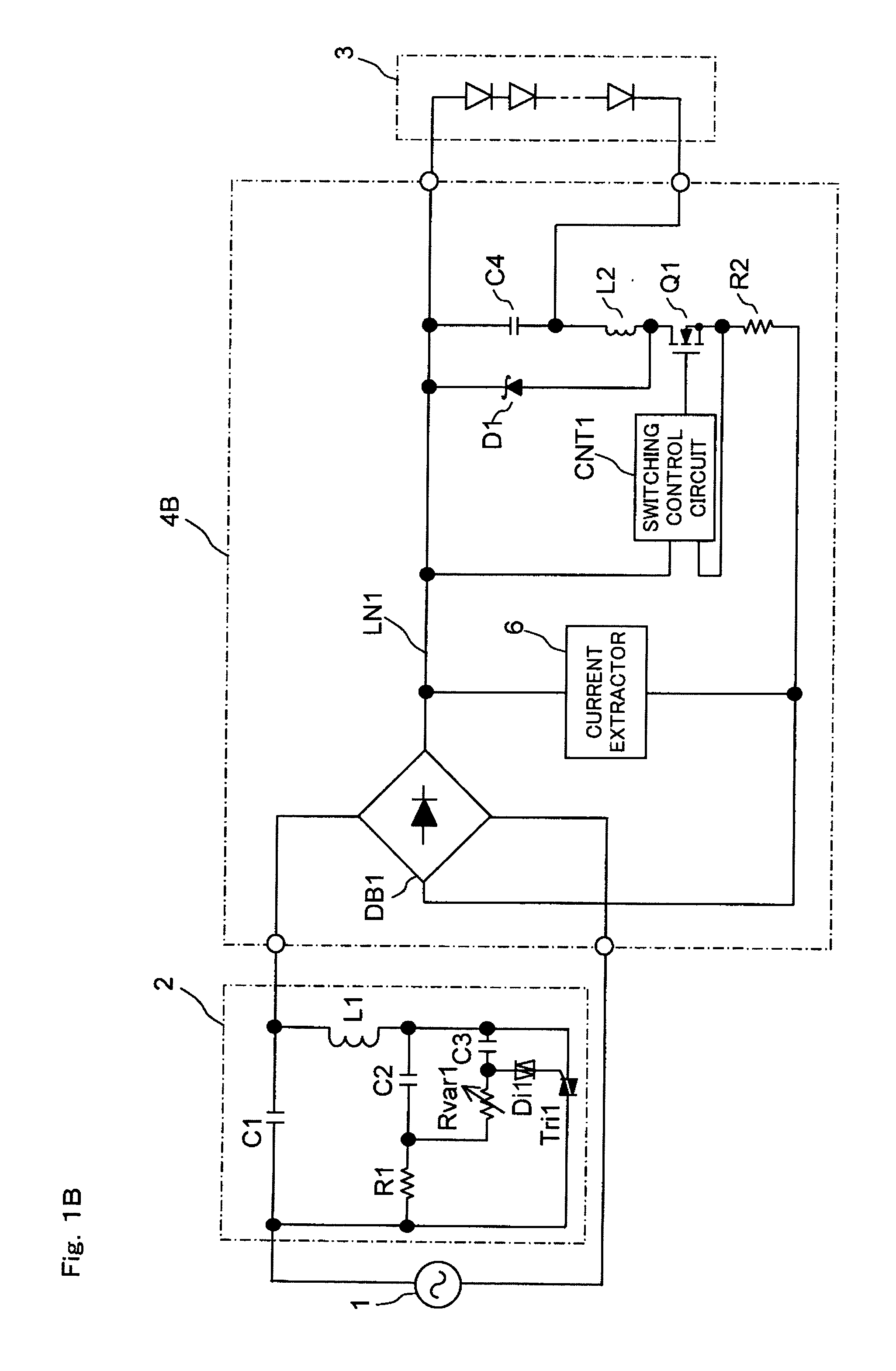
[0070]FIG. 1B shows the configuration of the LED illumination system according to a second embodiment of the present invention. The same reference symbols are used in FIG. 1B to refer to components that are the same as those in FIG. 18, and no detailed description thereof will be given. The LED illumination system according to the present invention shown in FIG. 1B is provided with a phase control dimmer 2, an LED module 3, and an LED drive circuit 4B. The LED drive circuit 4B is another example of the LED drive circuit according to the present invention, and is a switching-type LED drive circuit having a diode bridge DB1, a switching control circuit CNT1, a switching element Q1, a coil L2, a diode D1, a capacitor C4, a resistor R2, and a current extractor 6. The current extractor 6 is provided between the output terminals of the diode bridge DB1, and extracts a current from a power supply feed line LN1 for feeding an LED drive current to the LED module 3 during operation. In the LE...

third embodiment

[0072]FIG. 2 shows the configuration of the LED illumination system according to a third embodiment of the present invention. The same reference symbols are used in FIG. 2 to refer to components that are the same as those in FIG. 17, and no detailed description thereof will be given. The LED illumination system according to the third embodiment of the present invention shown in FIG. 2 is provided with a phase control dimmer 2′, an LED module 3, and an LED drive circuit 4. The LED drive circuit 4 is a direct-type (non-switching type) LED drive circuit, and has a diode bridge DB1 and a current limiting circuit 5. In the LED illumination system according to the third embodiment of the present invention shown in FIG. 2, the phase control dimmer 2′ is provided between an alternating-current power supply 1 and the input terminal of the LED drive circuit 4, and the LED module 3 composed of one or more LED elements is provided between the output terminals of the LED drive circuit 4.

[0073]Th...


PUM


Abstract

An LED drive circuit for driving an LED by input of an alternating voltage, the LED drive circuit being capable of connecting to a phase control dimmer. The LED drive circuit is provided with a current extractor for continuing to allow current to flow into the phase control dimmer so that a phase control element inside the phase control dimmer does not switch off before the alternating voltage reaches 0 V after the phase control element inside the phase control dimmer switches on and the LED emits light.

Description

[0001]This nonprovisional application claims priority under 35 U.S.C. §119(a) on Patent Application No. 2009-295028 filed in Japan on Dec. 25, 2009, the entire contents of which are hereby incorporated by reference.BACKGROUND OF THE INVENTION[0002]1. Field of the Invention[0003]The present invention relates to an LED drive circuit for driving an LED (Light Emitting Diode), to a phase control dimmer which can be connected to the LED drive circuit, and to an LED illumination fixture, LED illumination device, and LED illumination system having an LED as a light source.[0004]2. Description of the Related Art[0005]An LED has such characteristics as low current consumption and long service life, and LED applications are expanding not only to display devices but also to illumination fixtures and other applications. In LED illumination fixtures, a plurality of LED units is often used in order to obtain the desired lighting intensity.[0006]Common illumination fixtures usually use a commercia...

Claims


Application Information

Patent Timeline
Patent Type & Authority Applications(United States)
IPC IPC(8): H05B37/02
CPCH05B33/0809H05B33/0815Y02B20/348H05B37/0263H05B33/0845H05B47/185H05B45/10Y02B20/30H05B45/3725
Inventor KANAMORI, ATSUSHIKUBO, MASARUMARUYAMA, YASUHIROWARITA, HIROHISA
Owner SHARP KK
Why Eureka
Try Eureka