Parking brake control unit

a technology for controlling units and parking brakes, applied in braking systems, instruments, analogue processes for specific applications, etc., can solve the problems of large service brake application, insufficient consideration of brake force generated by drivers pressing brake pedals, and inability to meet tough requirements

Active Publication Date: 2010-03-25
ADVICS CO LTD
View PDF6 Cites 47 Cited by
  • Summary
  • Abstract
  • Description
  • Claims
  • Application Information

AI Technical Summary

Benefits of technology

[0009]In light of the foregoing, the present invention provides a parking brake control unit that is capable of, when brake force is generated by a parking brake and a service brake compensates for the brake force, inhibiting generation of a brake force larger than necessary.
[0011]In this manner, the correction unit corrects the target pressing force such that as the brake force generated by the service brake becomes larger, the target pressing force becomes smaller. With this correction, when brake force is generated by the electric parking brake and the service brake compensates for the brake force, it is possible to inhibit generation of a brake force larger than necessary.
[0013]In this manner, if the target pressing force is not changed after the correction, it is possible to inhibit the lock control from becoming unstable due to changes in the target pressing force after the correction.
[0015]Further, according to a fourth aspect of the present invention, as a physical quantity corresponding to the pressing force, a motor current that flows through the electric motor may be detected. In this case, in the lock control unit, the motor current generated before the friction member comes into contact with the friction receiving member may be set as a no load current, and a value obtained by adding a target motor current value increase amount to the no load current may be set as the target pressing force. Further, the drive of the electric motor may be stopped when an increase amount of the motor current from the no load current exceeds the target motor current value increase amount. The correction unit may correct the target pressing force by correcting the target motor current value increase amount such that as the brake force generated by the service brake becomes larger, the target motor current value increase amount becomes smaller.

Problems solved by technology

However, when the service brake compensates for the insufficient brake force of the parking brake as described in JP-T-2007-519568, the magnitude of the service brake application, namely, the brake force generated by a driver depressing a brake pedal is not taken into consideration.
Therefore, when the driver depresses the brake pedal with a large depression force, there is a possibility that the brake force generated when the parking brake is applied will be larger than necessary.
As a result, tough requirements need to be satisfied, and the size and weight of the brake caliper and the parking brake actuator are increased.

Method used


Image

  • Parking brake control unit
  • Parking brake control unit
  • Parking brake control unit

Examples


first embodiment

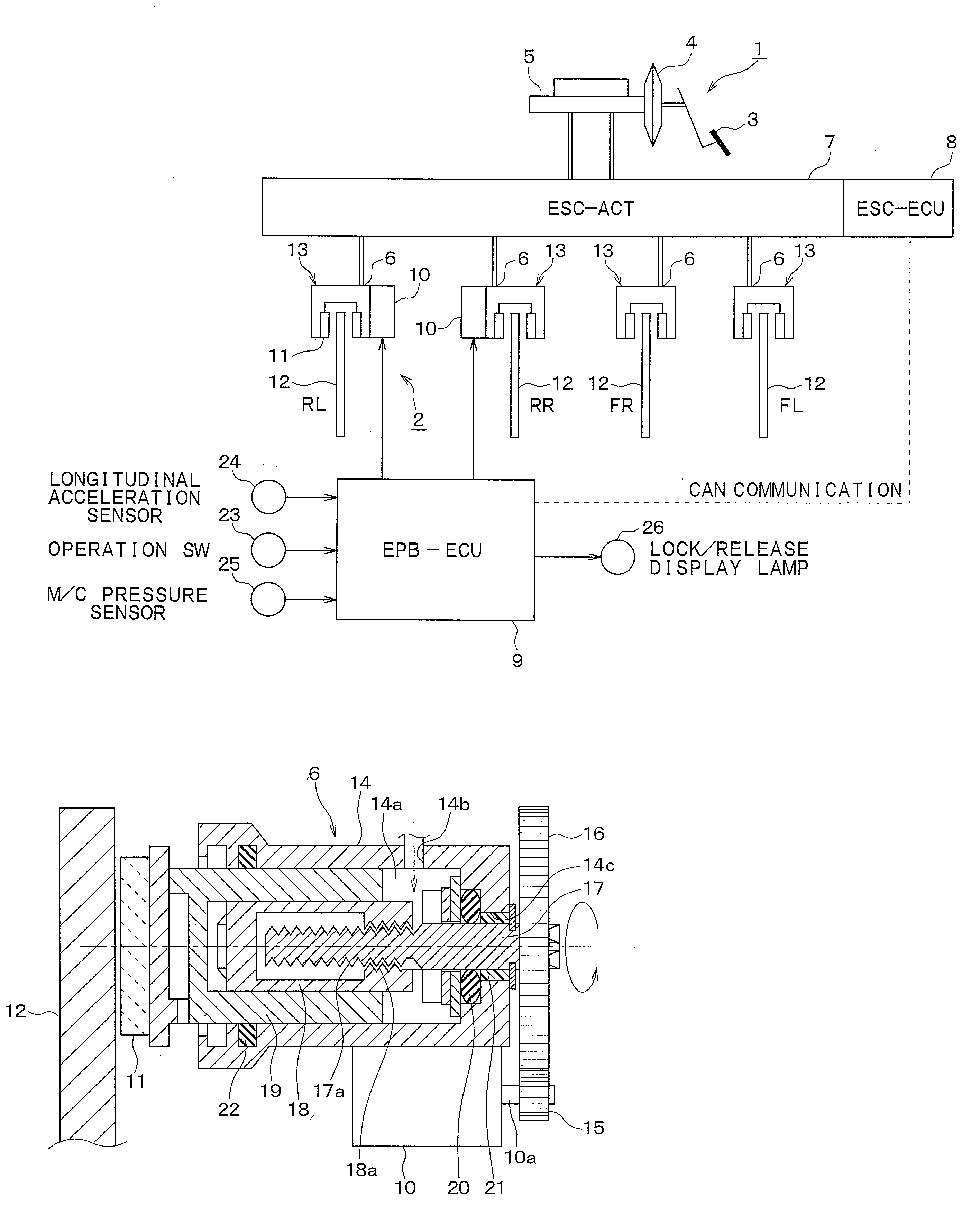
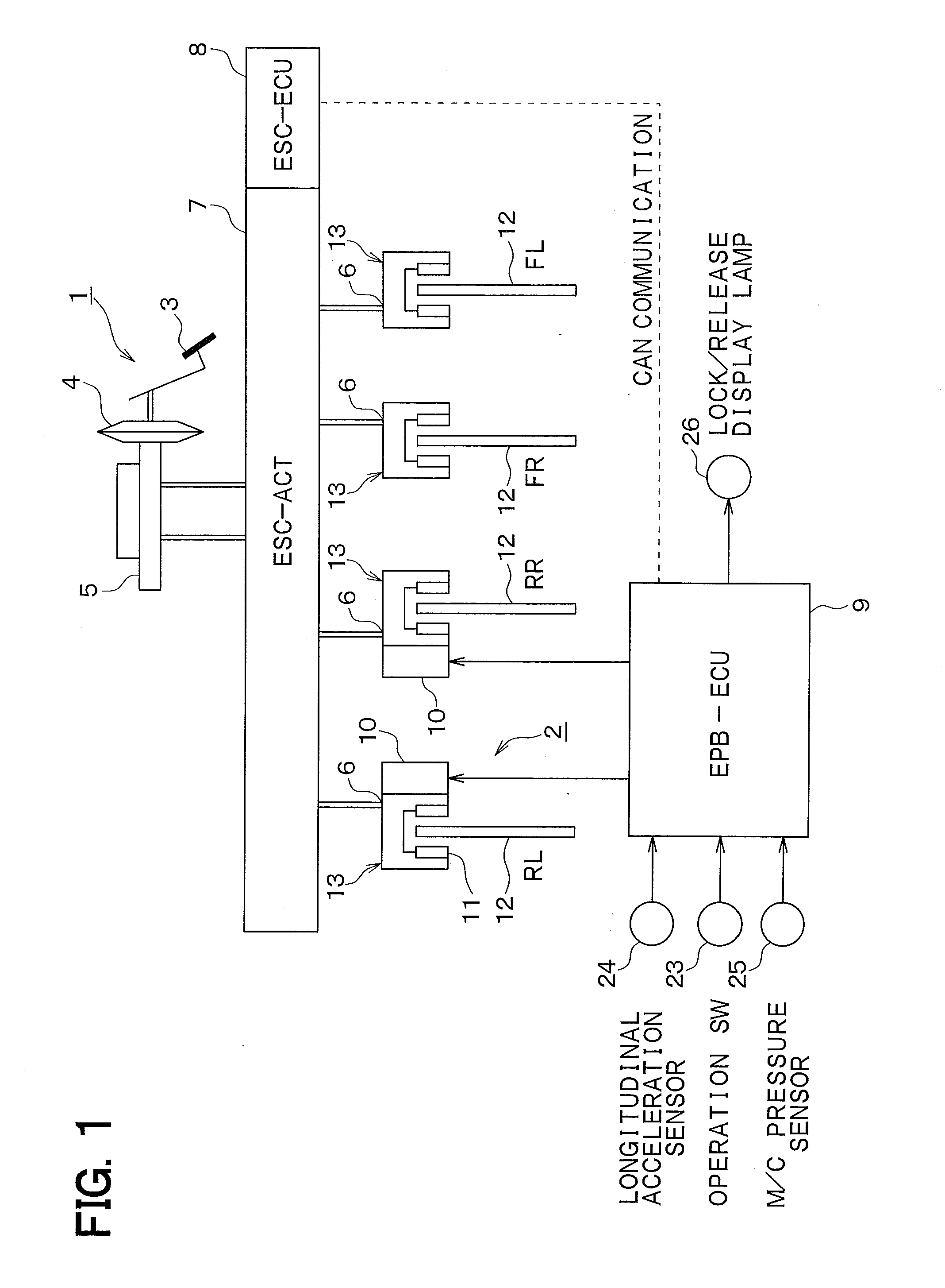
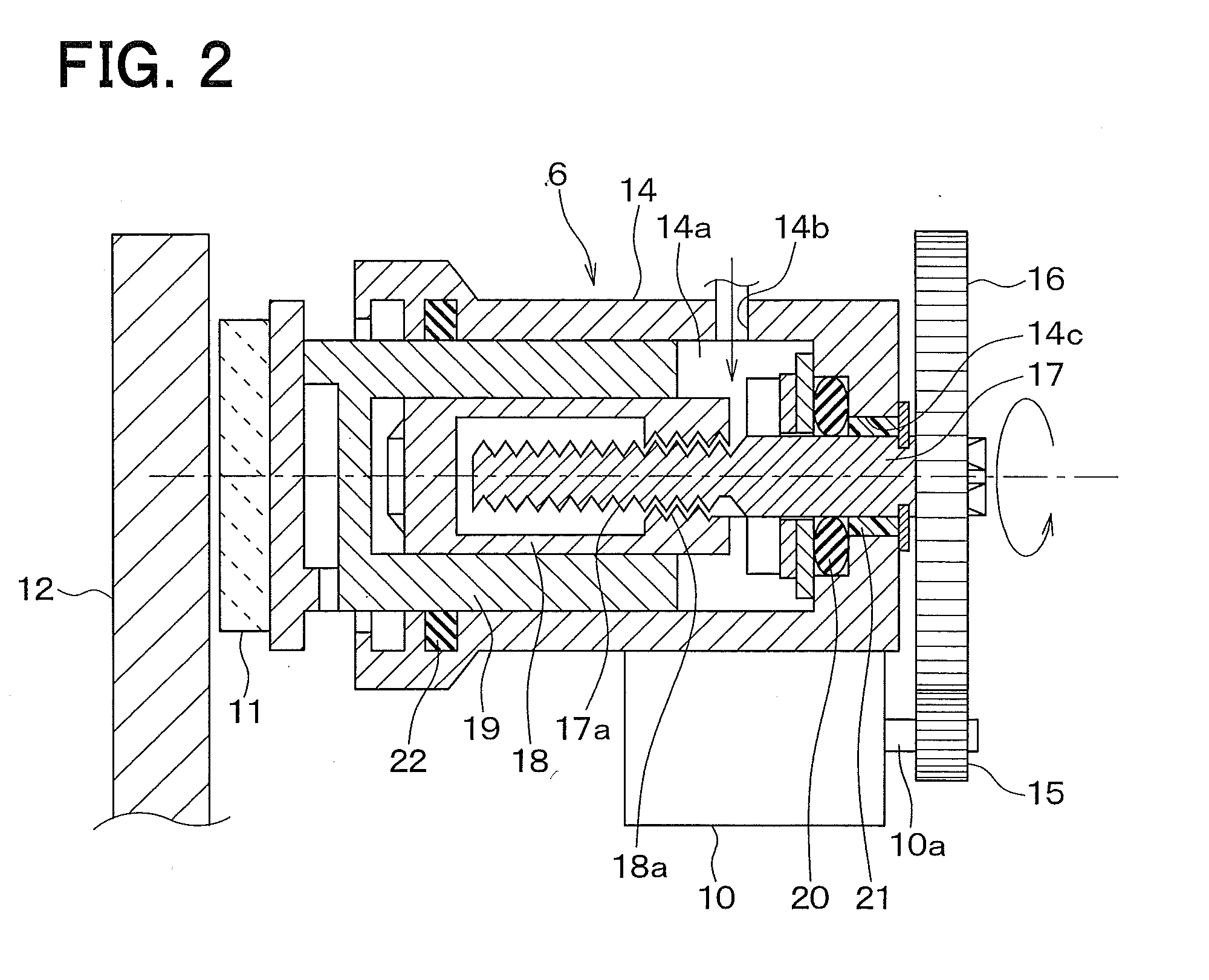
[0029]A first embodiment of the present invention will be described. In the present embodiment, a vehicle brake system in which an electric parking brake (EPB) using a disk brake is applied to a rear wheel system will be described as an example. FIG. 1 is a schematic diagram showing an overview of a vehicle brake system, to which a parking brake control unit according to the present embodiment is applied. FIG. 2 is a sectional schematic diagram showing a rear wheel brake mechanism provided in the brake system. The present embodiment will now be described with reference to FIG. 1 and FIG. 2.

[0030]As shown in FIG. 1, the brake system is provided with a service brake 1 that generates a brake force based on a pedal depression force of a driver, and an EPB 2 that restricts movement of the vehicle when it is parked.

[0031]The service brake 1 boosts the pedal depression force in accordance with the depression of a brake pedal 3 by the driver using a brake booster 4, and generates brake hydr...


PUM


Abstract

When a brake force is generated by a service brake in accordance with the depression of a brake pedal by a driver, a brake force generated by an electric parking brake is reduced when lock control is performed, taking the brake force generated by the service brake into consideration. More specifically, a target motor current value increase amount is corrected such that as the brake force generated by the service brake becomes larger, the target motor current value increase amount becomes smaller. Thus, when brake force is generated by the electric parking brake and the service brake compensates for the brake force, it is possible to inhibit generation of a brake force larger than necessary.

Description

CROSS REFERENCE TO RELATED APPLICATION[0001]This application is based upon and claims the benefit of Japanese Patent Application No. 2008-243963 filed on Sep. 24, 2008, the content of which are incorporated herein by reference.BACKGROUND OF THE INVENTION[0002]1. Field of the Invention[0003]The present invention relates to a parking brake control unit that performs lock control of an electric parking brake (EPB).[0004]2. Description of the Related Art[0005]Generally, parking brakes are used to restrict the movement of parked vehicles. Various parking brakes are known, such as, for example, manual parking brakes that transmit an operation force to a brake mechanism by pulling a brake cable using a control lever, and electric parking brakes that transmit motor torque to a brake mechanism by pulling a cable using the torque of the motor.[0006]When an electric parking brake (EPB) is locked, a motor is rotated to a locked side (positive rotation) so as to transmit the motor torque to a br...

Claims


Application Information

Patent Timeline
Patent Type & Authority Applications(United States)
IPC IPC(8): B60T13/00F16D65/18
CPCB60T13/741B60T13/588
Inventor KONDO, KAZUMAWATANABE, TAKASHI
Owner ADVICS CO LTD
Why Eureka
Try Eureka