
Video monitoring method and system based on interactive voice response (IVR) technology

A technology of video surveillance system and interactive voice, applied in CCTV system, transmission system, TV and other directions to achieve the effect of enriching access methods and expanding user groups

Inactive Publication Date: 2011-08-31
HUAWEI TECH CO LTD
View PDF8 Cites 10 Cited by
  • Summary
  • Abstract
  • Description
  • Claims
  • Application Information

AI Technical Summary

Benefits of technology

This innovation allows two different types of devices (IVR) or monitors together - one device called an audio/video recorder that plays back recorded content from another monitored area while also being able to play it on other screens like TVs without interferring them. Users have this ability to watch videos remotely at their own pace instead of sitting next to each machine individually. Additionally, they only require a special phone number when accessing these systems because there are no extra steps needed beforehand. Overall, this new design improves efficiency and flexibility in managing large amounts of data collected over time.

Problems solved by technology

The technical problem addressed in this patented text relates to traditional video monitoring system that requires specialized hardware devices like cameras attached to computers or smartphones used by people who want secure online communication with each other over networks such as internet connections.

Method used


Image

  • Video monitoring method and system based on interactive voice response (IVR) technology
  • Video monitoring method and system based on interactive voice response (IVR) technology
  • Video monitoring method and system based on interactive voice response (IVR) technology

Examples


Embodiment 1

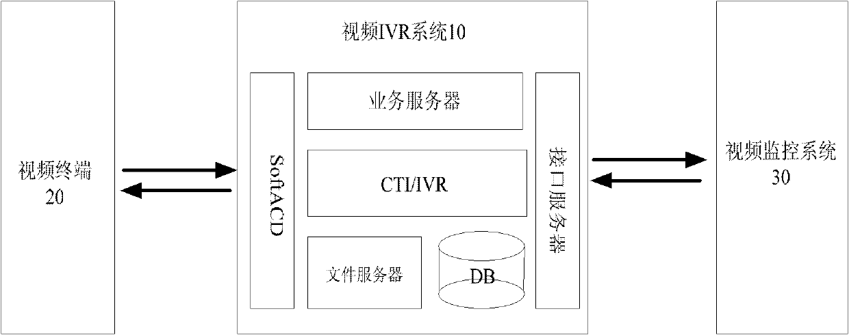
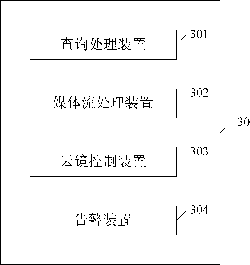
[0020] The present embodiment provides a video monitoring system based on interactive voice response IVR technology, figure 1 It is a structure diagram of the video monitoring system based on the interactive voice response IVR technology in this embodiment. Such as figure 1 As shown, the system includes: a video IVR system 10 , and a video monitoring system 30 connected to the video IVR system 10 . In addition, the system also includes a video terminal 20 .

[0021] The video IVR system 10 of this embodiment can be a value-added platform that provides integrated audio and video services for 3G video terminal users based on WCDMA circuit domain 3G-324M video calls; The video surveillance system requests video streaming and PTZ control. In video surveillance applications, PTZ control represents pan-tilt omni-directional (up and down, left and right) movement and lens zoom and zoom control. By controlling the pan-tilt, the zoom of the lens, the change of the aperture, the rot...

Embodiment 2

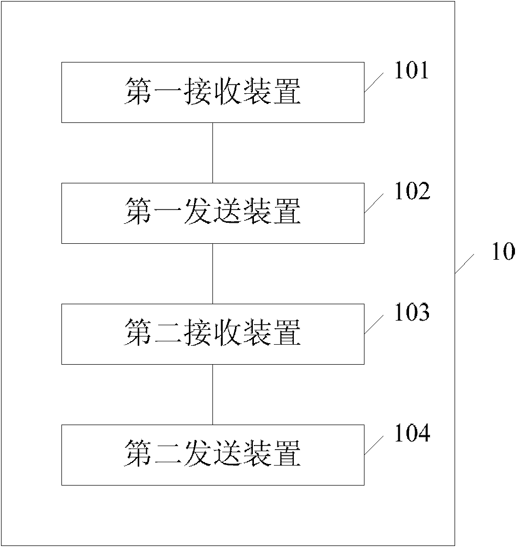
[0038] Corresponding to the system in Embodiment 1, this embodiment also provides a video monitoring method based on IVR technology. figure 2 is a signaling flowchart of the method. Such as figure 2 As shown, the method includes:

[0039] S201. The video IVR system receives a video call request sent by a video terminal, where the video call request includes an identifier of the video terminal and a video call service code;

[0040] S202. The video IVR system queries the video monitoring system for a list of monitoring devices corresponding to the video terminal according to the identification of the video terminal and the video call service code;

[0041] S203. The video IVR system receives the monitoring device list corresponding to the video terminal returned by the video monitoring system, and provides it to the video terminal;

[0042] S204. According to the selection of the monitoring device by the video terminal, the video IVR system obtains the media stream monitor...


PUM


Abstract

The invention provides a video monitoring method and system based on an interactive voice response (IVR) technology. The method comprises the following steps: a video IVR system receives a video calling request transmitted by a video terminal, wherein the video calling request contains an identifier and a video calling business code of the video terminal; the video IVR system inquires a monitoring equipment list corresponding to the video terminal in the video monitoring system according to the identifier and the video calling business code of the video terminal; the video IVR system receives the monitoring equipment list corresponding to the video terminal and being returned by the video monitoring system and provides the monitoring equipment list to the video terminal; and the video IVR system selects the monitoring equipment according to the video terminal, obtains a media stream monitored by the selected monitoring equipment from the video monitoring system and provides the media stream to the video terminal to be played.

Description


Claims


Application Information

Patent Timeline
Owner HUAWEI TECH CO LTD
Learn More