Electric shaver

一种剃刀、搭条的技术,应用在电剃刀领域,能够解决导入性能不太好、起毛部难以进入等问题

Active Publication Date: 2011-09-28
PANASONIC CORP
View PDF10 Cites 0 Cited by
  • Summary
  • Abstract
  • Description
  • Claims
  • Application Information

AI Technical Summary

Problems solved by technology

[0003] However, in the above-mentioned prior art, since a plurality of straps are formed so that their respective skin-contacting surfaces are included on the same plane, it is difficult for the raised portion provided on the straps to enter under the fallen body hair (between the body hair and the skin surface). between)
That is, in the prior art described above, the lead-in performance of the lodging body hair with respect to the outer blade is not so good.

Method used


Image

  • Electric shaver
  • Electric shaver
  • Electric shaver

Examples


no. 1 approach

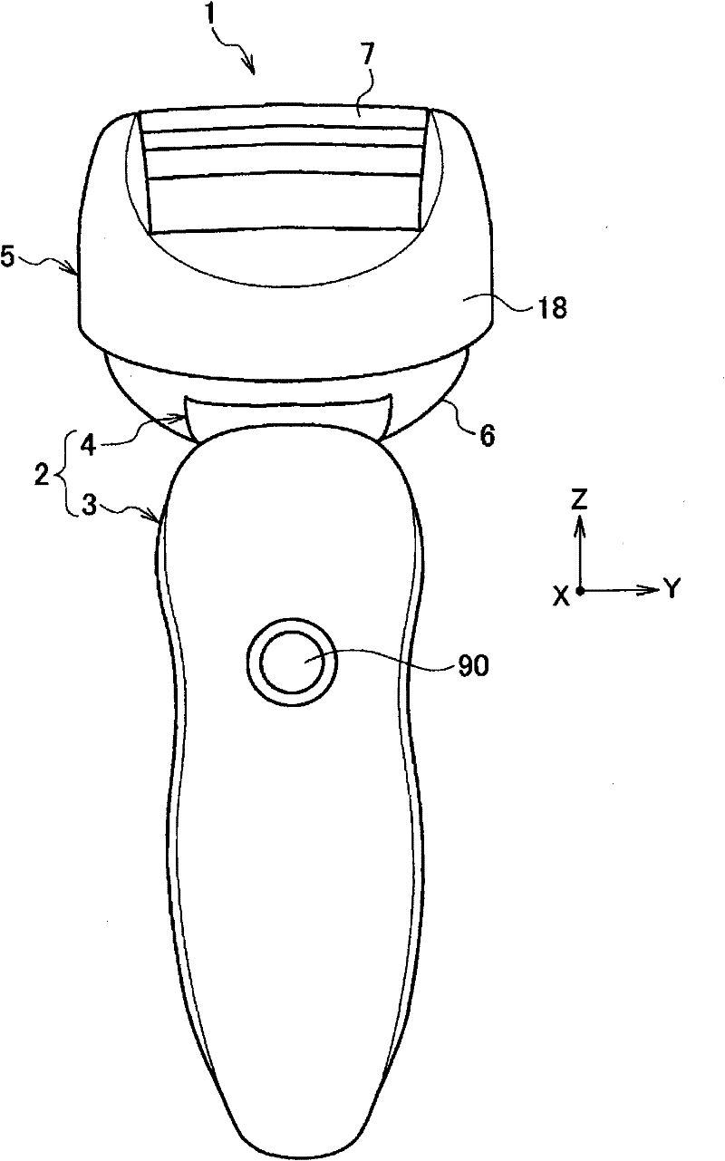
[0033] like figure 1 As shown, the electric shaver 1 of the present embodiment includes a handle 2 to be held by hand, and a head 5 fixed to the handle 2 .

[0034] The handle portion 2 includes a synthetic resin handle body 3 in which a battery (not shown) is incorporated, and a synthetic resin handle connecting portion 4 protruding rearward from the upper surface of the handle body 3 . In addition, at least any one of a known left-right swing mechanism and a known front-back swing mechanism may be provided on the upper surface of the handle connecting portion 4, so that the head 5 can be installed in a swingable manner in the left-right direction or in the front-rear direction. on handle 2.

[0035] The head 5 includes a linear head 6 that incorporates a linear motor (not shown) and is connected to the handle connecting portion 4 , and a blade unit 7 attached to the linear head 6 . and, if figure 1 As shown, a switch portion 90 for turning on and off the drive of the line...

no. 2 approach

[0113] As shown in FIG. 22 , the mesh blades 9H, 10H, and 12H of the present embodiment basically have substantially the same configuration as the mesh blades 9 , 10 , and 12 of the first embodiment described above.

[0114] That is, the mesh blades 9H, 10H, and 12H are formed by dividing the long plate-shaped members 9cH, 10cH, and 12cH (see FIG. It is bent and formed in an inverted U-shape along the front-rear direction (shaving direction) X so as to be convex.

[0115] And, the longitudinal direction strap part 42 (the strap part 40) is equipped with: be provided with the raising part (in this embodiment, Side 43c and side 44c are equivalent to the length direction take-up section (raised take-up section) 45 of the big raised section 45c of the raising force of the raised section); The skin contacting surface 45j of the skin contacting surface 45j is near the longitudinal direction strap portion (the first strap portion) 43 on the position of the inner blade 13 side; 45j ...

no. 3 approach

[0126] In this embodiment, an example in which the present invention is applied to a rotary electric shaver will be described.

[0127] The main difference between the electric shaver 1I of this embodiment and the above-mentioned first embodiment is that the inner blade 13I is a rotating blade.

[0128] This electric shaver 1I includes an outer blade 8I, and an inner blade 13I that is disposed inside the outer blade 8I (below the outer blade 8I) and relatively moves relative to the outer blade 8I. The outer blade 8I and the inner blade 13I are each formed in a circular shape, and the inner blade 13I rotates in the rotation direction (direction b) with respect to the outer blade 8I fixed on the main body side. Then, the body hair 71 inserted into the blade hole 50 of the outer blade 8I is cut by the cooperative operation of the outer blade 8I and the inner blade 13I.

[0129] In the present embodiment, a plurality of radially elongated substantially rectangular cutting holes 7...


PUM


Abstract

An electric shaver (1) includes : outer blades (8) having blade holes (50) defined by bars; and inner blades (13) which is provided inside of the outer blades (8) and moved relative to the outer blades (8) to cut body hair (71) inserted into the blade holes (50). A first bar (43) in which a skin contact surface (43a) coming into contact with skin (70) is positioned on the inner blade (13) side ofa skin contact surface (45j) of a hair raising bar (45) is provided adjacent to and forward of the hair raising bar (45).

Description

technical field [0001] The present invention relates to electric razors. Background technique [0002] Currently, various electric razors for shaving body hair have been developed. Here, the angle formed by the extension direction of the body hair and the skin surface is called the hair angle. Body hair with a large hair angle (for example, 45° to 60°) is easy to shave, and body hair with a small hair angle (for example, 30° or less) is easy to shave. Body hair has the problem of being difficult to shave. Therefore, as disclosed in Japanese Patent No. 3083548, develop the electric shaver that is provided with the hair raising portion that the hair raising force that makes the body hair that falls down stand up is bigger than prior art on the bar portion (stack portion) of outer blade. [0003] However, in the above-mentioned prior art, since a plurality of straps are formed so that their respective skin contact surfaces are included on the same plane, it is difficult for t...

Claims


Application Information

Patent Timeline
Patent Type & Authority Applications(China)
IPC IPC(8): B26B19/00B26B19/38
CPCB26B19/384
Inventor 岩崎重左门清水宏明小林升小森俊介生田利夫
Owner PANASONIC CORP
Why Eureka
Try Eureka