LED driving control circuit and method

A LED drive and control circuit technology, applied in the direction of electric lamp circuit layout, electric light source, lighting device, etc., can solve the problems of life impact, unfavorable design, easy flickering of the power grid, etc., to facilitate the output current and solve the effect of LED light flickering

Active Publication Date: 2011-09-28
HANGZHOU SILAN MICROELECTRONICS
View PDF4 Cites 88 Cited by
  • Summary
  • Abstract
  • Description
  • Claims
  • Application Information

AI Technical Summary

Problems solved by technology

This current characteristic is not conducive to the design of the lighting system, and also has a

Method used


Image

  • LED driving control circuit and method
  • LED driving control circuit and method
  • LED driving control circuit and method

Examples


specific Embodiment approach

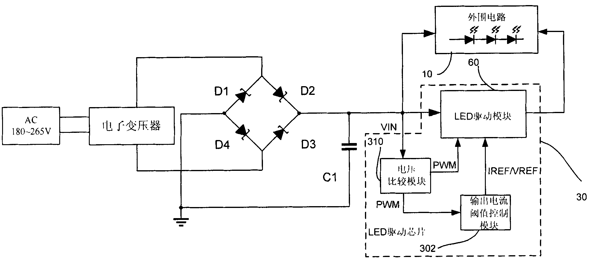
[0072] The output current threshold control module 302 includes:

[0073] The first inverter I31 inputs the comparison signal PWM output by the voltage comparison module 310, and the output of the first inverter I31 is the inversion signal PWM0 of the comparison signal PWM;

[0074] The first transmission gate I32 inputs the third reference voltage VREF3, the inversion signal PWM0 and the comparison signal PWM signal as the switching signal of the transmission gate;

[0075] The second transmission gate I33, the input signal is ground, the inversion signal PWM0 and the comparison signal PWM are used as the switching signals of the second transmission gate I33;

[0076] The output of the first transmission gate I32 and the output of the second transmission gate I33 are connected together to provide a filter circuit, and the filter circuit filters the switching signals output by the first transmission gate and the second transmission gate into a direct current, and the output of...


PUM


Abstract

The invention discloses an LED driving control circuit and a method. The LED driving control circuit comprises a voltage comparison module, an output current threshold control module and an LED driving module, wherein the voltage comparison module is used for generating a comparison signal PWM (Pulse-Width Modulation) and providing the comparison signal PWM to the output current threshold control module and the LED driving module; the output current threshold control module is used for generating current threshold control signal IREF/VREF (Input Reference/Voltage Reference) to the LED driving module according to the duty factor of the comparison signal PWM; and the LED driving module is used for generating an LED driving control signal according to the input current threshold control signal IREF/VREF and the comparison signal PWM. The product of the duty factor of the current threshold control signal IREF/VREF and the duty factor of the comparison signal PWM is a constant so that average current output by the LED driving control circuit is equal under the comparison signal PWM of different duty factors. According to the invention, the influence of the overlarge current change of an LED lamp when a commercial power is changed can be solved; output current can be set conveniently; and the flickering problem of the LED lamp resulted from the current change is solved.

Description

technical field [0001] The invention relates to the field of LED drive circuits, in particular to the LED drive circuit technology using an electronic transformer as a power supply to supply power to LED lamps. Background technique [0002] LED drive circuits, especially high-power LED drive circuits, have been widely used in spotlights, landscape lighting, automotive lighting, fluorescent lamps and other fields. Traditional halogen lamps consume a lot of power, have a short lifespan, and are polluting. Therefore, it is a trend to replace halogen lamps with LED lamps in recent years. [0003] Since traditional halogen lamps are powered by electronic transformers, the output of electronic transformers is a good choice for halogen lamps with resistive characteristics, but if LED lamps are used instead of halogen lamps, it is necessary to solve the problem of electronic transformers as power supplies for LEDs The problem. [0004] figure 1 It is a schematic diagram of an LED...

Claims


Application Information

Patent Timeline
IPC IPC(8): H05B37/02
Inventor 王栋吴建兴
Owner HANGZHOU SILAN MICROELECTRONICS
Why Eureka
Try Eureka