Method and device for monitoring optical layer of passive optical network based on two-dimensional optical orthogonal code

A technology of passive optical network and optical orthogonal code, which is applied to the selection device of multiplexing system, selection device, electromagnetic wave transmission system, etc.

Active Publication Date: 2011-10-19
SOUTHEAST UNIV
View PDF2 Cites 19 Cited by
  • Summary
  • Abstract
  • Description
  • Claims
  • Application Information

AI Technical Summary

Problems solved by technology

This makes these methods have various difficulties in practical application.

Method used


Image

  • Method and device for monitoring optical layer of passive optical network based on two-dimensional optical orthogonal code
  • Method and device for monitoring optical layer of passive optical network based on two-dimensional optical orthogonal code
  • Method and device for monitoring optical layer of passive optical network based on two-dimensional optical orthogonal code

Examples


Embodiment Construction

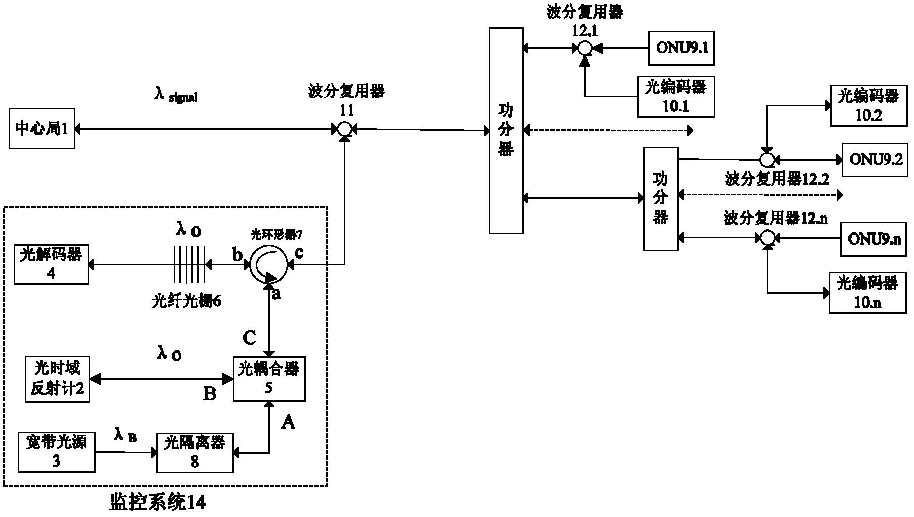
[0024] The monitoring schematic diagram of the centralized optical layer monitoring system combined with optical code division multiplexing technology in multi-cascaded PON is figure 1 .

[0025] A passive optical network based on two-dimensional optical orthogonal code optical layer monitoring, including: central office 1 and multiple users ONU9.1, ONU9.2, ..., ONU9.n, central office 1 and each user ONU9.1 , ONU9.2, ..., ONU9.n are connected by a power splitter, which is characterized in that a first-level wavelength division multiplexer 11 is provided on the backbone optical fiber between the central office 1 and the power splitter, The division multiplexer 11 is connected with the monitoring system 14, and the branch optical fibers between the power divider and each user ONU9.1, ONU9.2, ..., ONU9.n are respectively provided with first and second level wavelength division multiplexers 11.1, the second-level wavelength division multiplexer 11.2, ... and the n-level wavelengt...


PUM


Abstract

The invention provides a method and device for monitoring an optical layer of a passive optical network based on a two-dimensional optical orthogonal code. Each user is identified by using the two-dimensional optical orthogonal code. An optical encoder is added in the front of user equipment. The optical encoder performs optical encoding on a detected optical pulse and reflects an encoded optical signal to a monitoring system. The reflected optical signal is decoded in the monitoring system. The health state of each branch optical fibre is judged through the decoded signal. An optical power detection part in the monitoring system performs fault location and analysis functions simultaneously. In the invention, the link state of an optical network is monitored by adopting the passive optical device without limitation of a network topological structure and branch length. The device disclosed by the invention can identify that a fault is in the user equipment or an optical fibre link, judge the branch in which a fault is and position the specific position of the fault, and support the monitoring of the optical fibre link of the high-user-capacity passive optical network.

Description

technical field [0001] The invention belongs to the technical field of optical fiber communication. Specifically, in a passive optical network, an optical layer monitoring method and device based on a combination of two-dimensional optical orthogonal codes and reflected optical power detection. Background technique [0002] With the rapid development of fiber-to-the-home services, the Passive Optical Network (PON) is widely used in the optical access network. All users in the network use a common network structure, which makes the monitoring of network link performance more and more important. Faults in optical fiber links cannot be detected before the faults cause service interruptions at the application layer, so that huge losses to users and network operators cannot be avoided due to service interruptions. Optical layer monitoring technology can detect and locate faults in time when the performance of the physical layer deteriorates, and minimize the duration of faults,...

Claims


Application Information

Patent Timeline
Patent Type & Authority Applications(China)
IPC IPC(8): H04B10/08H04B10/12H04Q11/00H04B10/077
Inventor 孙小菡周谞
Owner SOUTHEAST UNIV
Why Eureka
Try Eureka