Multiloop combination-switch lever-type mechanical interlocking mechanism

A combination switch and interlocking mechanism technology, applied in the direction of air switch parts, etc., can solve the problems of complicated installation, loss of interlocking effect, and inability to open the large cover of the main cavity, and achieve the effect of ensuring safe operation and maintenance.

Inactive Publication Date: 2014-03-05
上海佳洲防爆电器有限公司
View PDF5 Cites 0 Cited by
  • Summary
  • Abstract
  • Description
  • Claims
  • Application Information

AI Technical Summary

Problems solved by technology

At present, in order to ensure safe operation of coal mine underground electrical equipment, one is a bolt fastening mechanism, such as figure 1 As shown, the existing bolt fastening mechanism adopts fastening bolts 13, the main cavity cover 12 is fixed on the switchgear 11 through the fastening bolts 13, the warning sign 14 is attached to the main cavity cover 12, and the isolation switch 15 is installed on the switchgear On equipment 11, the bolt fastening mechanism has a simple structure, but it is inconvenient to install and maintain, and it is not safe, so it must be guaranteed by a strict management system
The other is the quick door opening mechanism, most of which adopt lifting and left and right moving mechanisms. Most of the electrical and mechanical interlocks are designed in the form of gears and racks, sliders and springs, etc. The processing and installation of this mechanism are complicated. Once the spring fails, it will The slider will fail. After the slider fails, the main chamber cover will not be opened or the main chamber cover will not be closed when it is opened, and the interlocking function will eventually be lost.
At the same time, it can only be used for switchgear below the two main chamber covers
If the number of circuits is large and more than three large covers for the main cavity are required, this mechanism will be helpless

Method used


Image

  • Multiloop combination-switch lever-type mechanical interlocking mechanism
  • Multiloop combination-switch lever-type mechanical interlocking mechanism
  • Multiloop combination-switch lever-type mechanical interlocking mechanism

Examples


Embodiment Construction

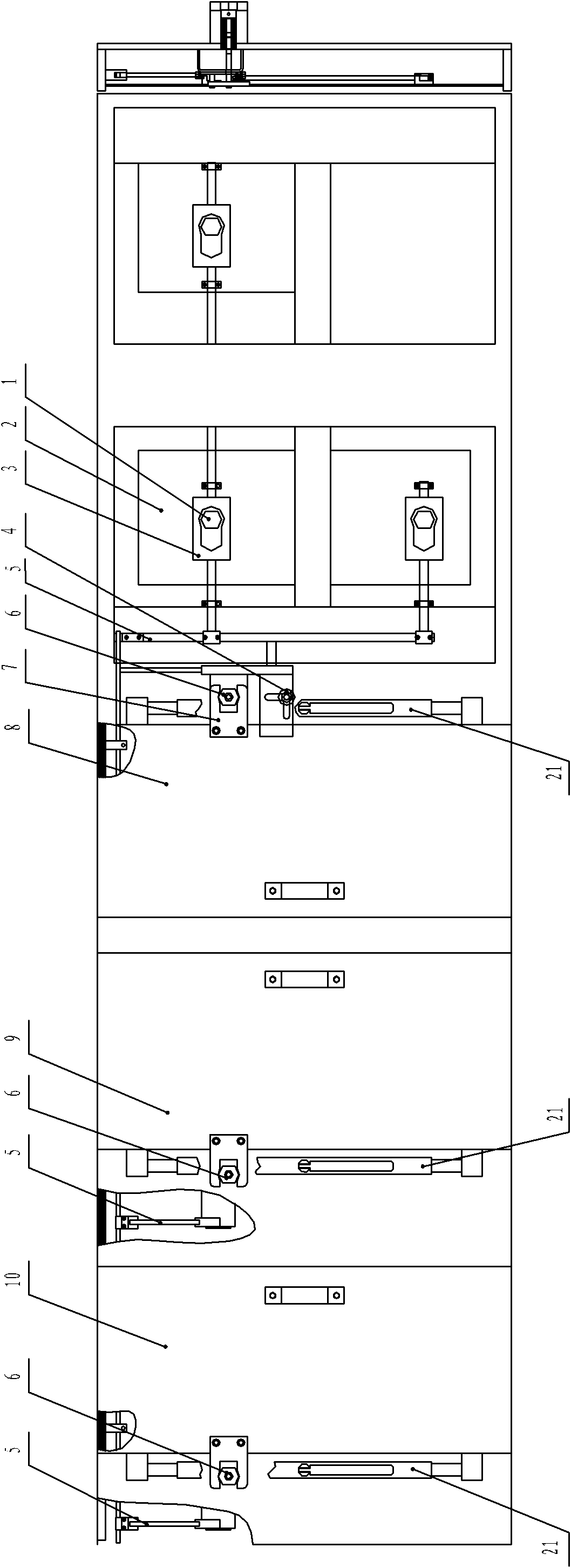
[0011] A preferred embodiment will be given below, and the present invention will be described more clearly and completely in conjunction with the accompanying drawings.

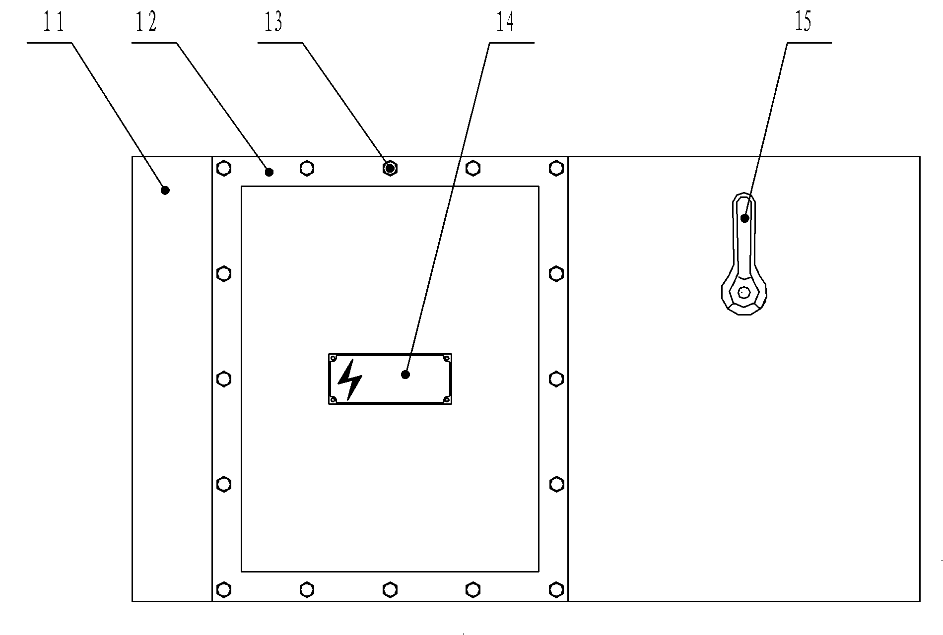
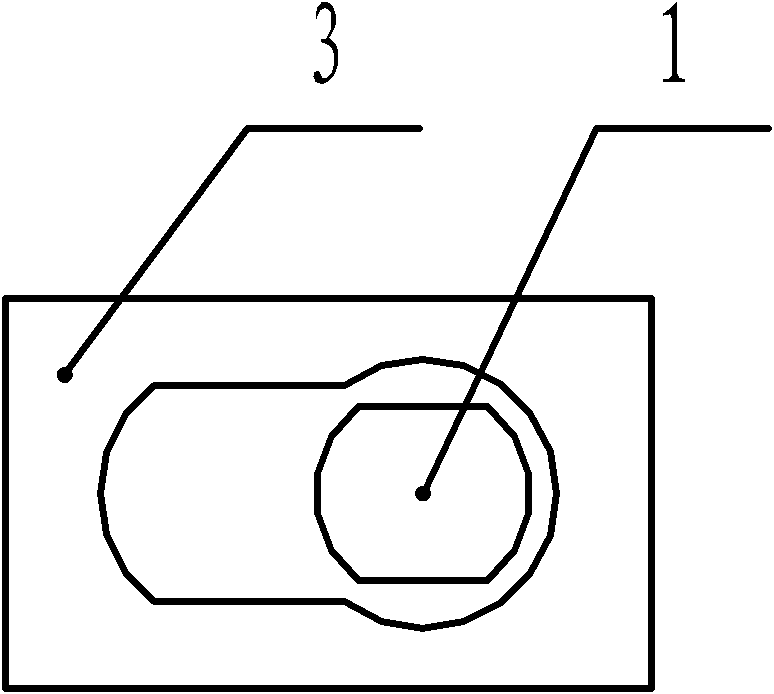
[0012] Such as figure 2 As shown, the multi-circuit combination switch lever mechanical interlock mechanism of the present invention includes a disconnector switch main shaft 1, a disconnector switch 2, an interlock slider 3, a first lever rotary mechanism 4, a connecting rod 5, and a second lever rotary mechanism 6 , the interlocking block 7, the first main cavity cover 8, the second main cavity cover 9, the third main cavity cover 10, the door opening mechanism 21, the isolating switch main shaft 1 is fixed on the isolating switch 2 and passes through the interlocking slide Block 3, the interlock slider 3 is slidably connected with the connecting rod 5, the second lever rotary mechanism 6 is slidably connected with the interlock block 7, the first lever rotary mechanism 4 is slidably connected with the co...


PUM


Abstract

The invention discloses a multiloop combination-switch lever-type mechanical interlocking mechanism which comprises an isolation switch spindle, an isolation switch, an interlocking slide block, a first lever rotary type mechanism, a connecting rod, a second lever rotary type mechanism, an interlocking block, a first main-chamber large cover, a second main-chamber large cover, a third main-chamber large cover, an opening mechanism. The isolation switch spindle is fixed on the isolation switch and passes through the interlocking slide block. The interlocking slide block is slidingly connected with the connecting rod. The second lever rotary type mechanism is slidingly connected with the interlocking block. The first lever rotary type mechanism is slidingly connected with the connecting rod. The first main-chamber large cover, the second main-chamber large cover and the third main-chamber large cover are arranged in series. The first main-chamber large cover and the third main-chamber large cover are fixed with the interlocking block. The opening mechanism is connected with the first main-chamber large cover, the second main-chamber large cover and the third main-chamber large cover. In the multiloop combination-switch lever-type mechanical interlocking mechanism of the invention, a lever work principle is adopted. And the mechanism is suitable for being installed and used in multiloop combination-switch equipment.

Description

technical field [0001] The invention relates to the technical field of explosion-proof multi-circuit combined switchgear, in particular to a lever-type mechanical interlocking mechanism of a multi-circuit combined switch. Background technique [0002] Coal mine underground electrical equipment clearly emphasizes that the main chamber cover cannot be opened when the electrical equipment is running underground. To open the main chamber cover, the power supply must be cut off first, and the main chamber cover must not be powered on when it is not closed. At present, in order to ensure safe operation of coal mine underground electrical equipment, one is a bolt fastening mechanism, such as figure 1 As shown, the existing bolt fastening mechanism adopts fastening bolts 13, the main cavity cover 12 is fixed on the switchgear 11 through the fastening bolts 13, the warning sign 14 is attached to the main cavity cover 12, and the isolation switch 15 is installed on the switchgear On...

Claims


Application Information

Patent Timeline
Patent Type & Authority Patents(China)
IPC IPC(8): H01H31/06
Inventor 易丰周常平湘刘学飞
Owner 上海佳洲防爆电器有限公司
Why Eureka
Try Eureka