Steel turning device

A technology of steel turning and turning mechanism, which is applied in the direction of feeding device, positioning device, storage device, etc., which can solve the problems of difficult steel turning over and polygonal steel turning over, and achieve reasonable structure, reliable action and accurate turning position Effect

Active Publication Date: 2011-11-23
浩中机械(蚌埠)有限公司
View PDF8 Cites 4 Cited by
  • Summary
  • Abstract
  • Description
  • Claims
  • Application Information

AI Technical Summary

Problems solved by technology

The deficiencies in the above steel turning device are: it can only turn over the steel with a circular cross section, but cannot turn over the steel with a polygonal cross section; it is difficult to turn over the steel with a large curvature

Method used


Image

  • Steel turning device
  • Steel turning device
  • Steel turning device

Examples


Embodiment Construction

[0009] The present invention is further described below in conjunction with embodiment and accompanying drawing.

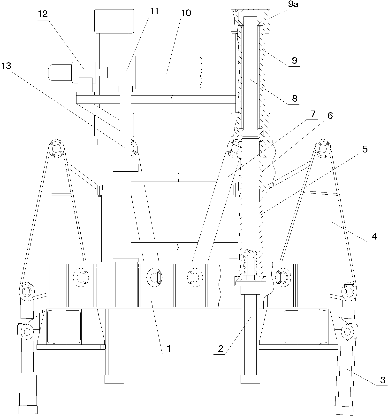
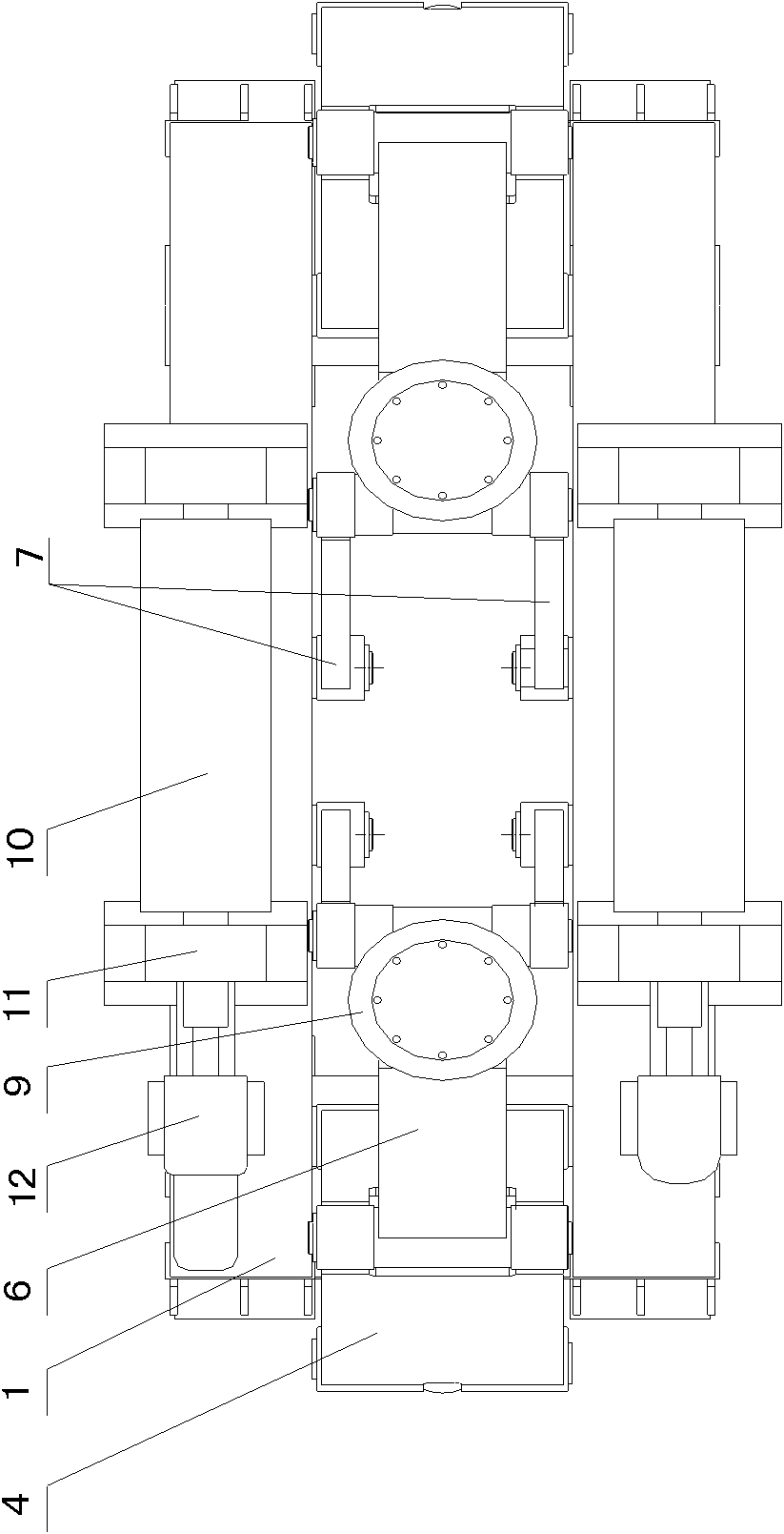
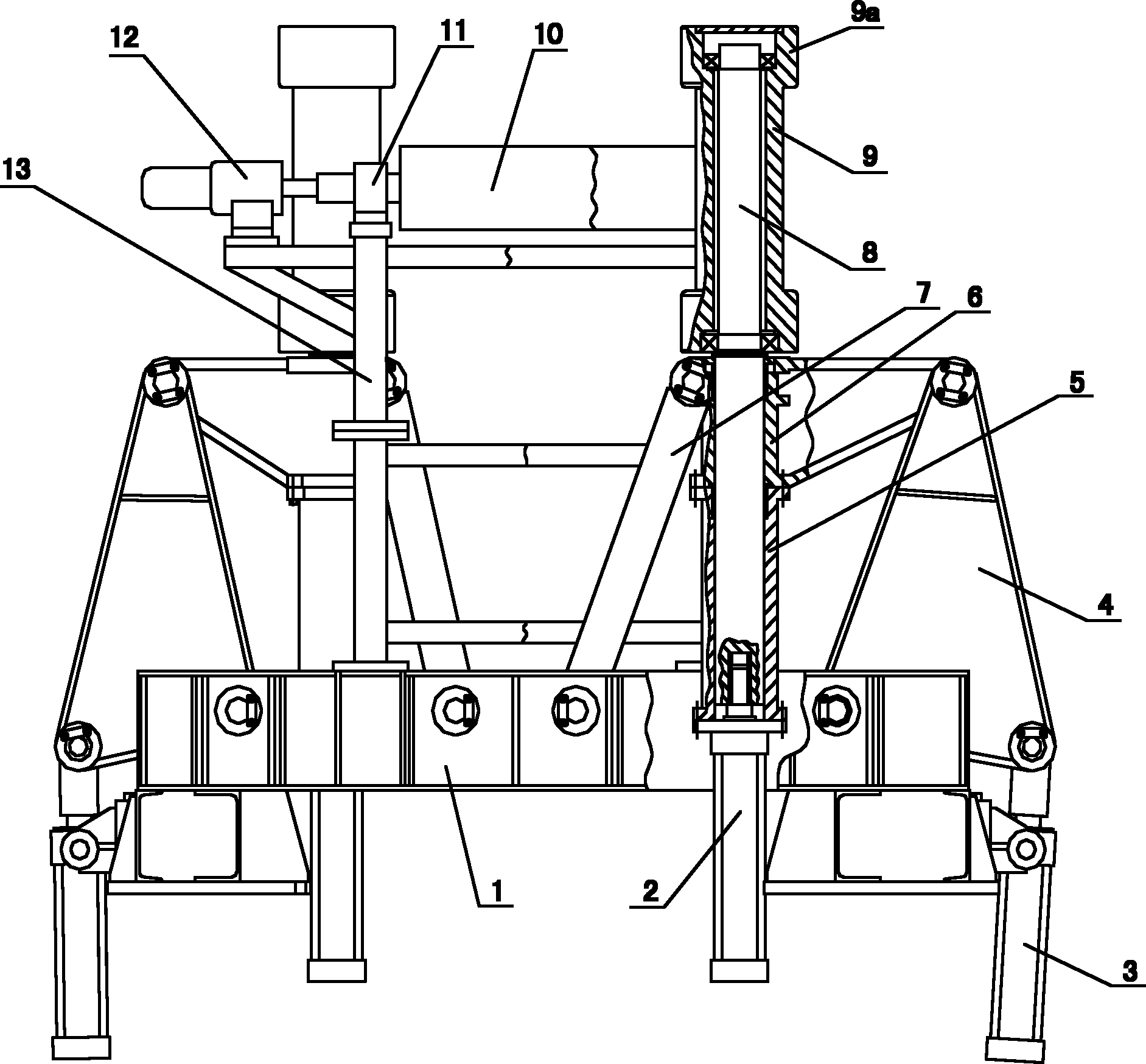
[0010] see figure 1 , figure 2

[0011] The steel-turning device provided by the present invention has a machine base 1, and the steel-turning mechanism provided on the machine base 1 has a pair of oppositely arranged rollers 9 in an upright shape, and each roller 9 is mounted on the upper end of a vertical shaft 8 and In cooperation with its rolling, each vertical shaft 8 is installed in a guide sleeve 6, the lower end of each guide sleeve 6 is connected with a first hydraulic cylinder 2 through the auxiliary guide sleeve 5, and the piston rod of the first hydraulic cylinder 2 is connected with the lower end of the vertical shaft 8 , the two sides of each guide sleeve 6 are respectively hinged with the upper end of a driving arm 4 and a pair of connecting rods 7, the lower ends of each driving arm 4 and connecting rod 7 are hinged with the base 1, and each gui...


PUM


Abstract

The invention discloses a steel turning device and is characterized in that a turning mechanism which is arranged on a base comprises a pair of upright rollers which are arranged face to face, each roller is arranged at the upper end part of a vertical shaft and in rolling fit with the vertical shaft, each vertical shaft is arranged inside a guide sleeve, a first hydraulic cylinder is connected at the lower end of each guide sleeve, the piston rods of the first hydraulic cylinders are connected at the lower ends of the vertical shafts, a driving arm and the upper ends of a pair of connecting rods are hinged on the two sides of each guide sleeve, and each driving arm and the lower end of each connecting rod are hinged with the base; each guide sleeve combines with the base and driving arm and connecting rod which are hinged with the guide sleeve, to form a parallelogram four-link mechanism; and two second hydraulic cylinders are fixed on the two sides of the frame respectively, and thepiston rods of the two second hydraulic cylinders are hinged with two driving arms respectively. When a steel material passes through the space between the pair of rollers, the driving arms are pushed upwards by the two second hydraulic cylinders, so that the rollers move in the opposite direction to closely clamp the steel material, and then the rollers are driven by the two first hydraulic cylinders to reversely move in the vertical direction, as a result, the steel material is turned.

Description

technical field [0001] The invention relates to steel processing equipment, in particular to a device for turning over steel. Background technique [0002] In the processing of strip steel, it is necessary to straighten the bent steel. At present, the straightening of steel is carried out by a straightening machine during the process of processing and transmitting steel. In order to align the protruding side of the bent part of the steel with the pressure head of the straightening machine, it is necessary to turn over by the steel turning device during the process of conveying the steel. The steel turning mechanism on an existing steel turning device consists of a pair of horizontally arranged rollers and a pressing arm driven by a power device. When the steel falls on the pair of rollers, the steel is pressed tightly by the pressing arm. Through the rotation of the rollers, the turning of the steel can be completed. The deficiencies in the above-mentioned steel turning d...

Claims


Application Information

Patent Timeline
Patent Type & Authority Applications(China)
IPC IPC(8): B21D43/00B21D3/00
Inventor 梁学楷李森林
Owner 浩中机械(蚌埠)有限公司
Why Eureka
Try Eureka