
Bisecting and marking gauge

A regular and symmetrical technology, applied in the field of division and planning, can solve the problems of troublesome use and low efficiency, and achieve the effect of overcoming trouble and low efficiency

Inactive Publication Date: 2011-11-23
车业好
View PDF0 Cites 5 Cited by
  • Summary
  • Abstract
  • Description
  • Claims
  • Application Information

AI Technical Summary

Problems solved by technology

[0002] In machinery manufacturing and other production fields, it is often encountered that the center of the workpiece is used as the positioning reference process. In order to achieve the requirements of the process, it is necessary to find the center of the workpiece or divide the circle of the workpiece during production. Line drawing. At present, in the field of production, to find the center of the workpiece, or to divide the circle of the workpiece, the generally used tools are compass and ruler, and the method of geometric line drawing is adopted. After many times of drawing This method can only find the corresponding points and lines after drawing lines many times. Therefore, it is not only troublesome to use, but also has the defect of low efficiency.

Method used


Image

  • Bisecting and marking gauge
  • Bisecting and marking gauge

Examples


Embodiment Construction

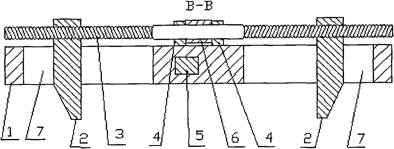
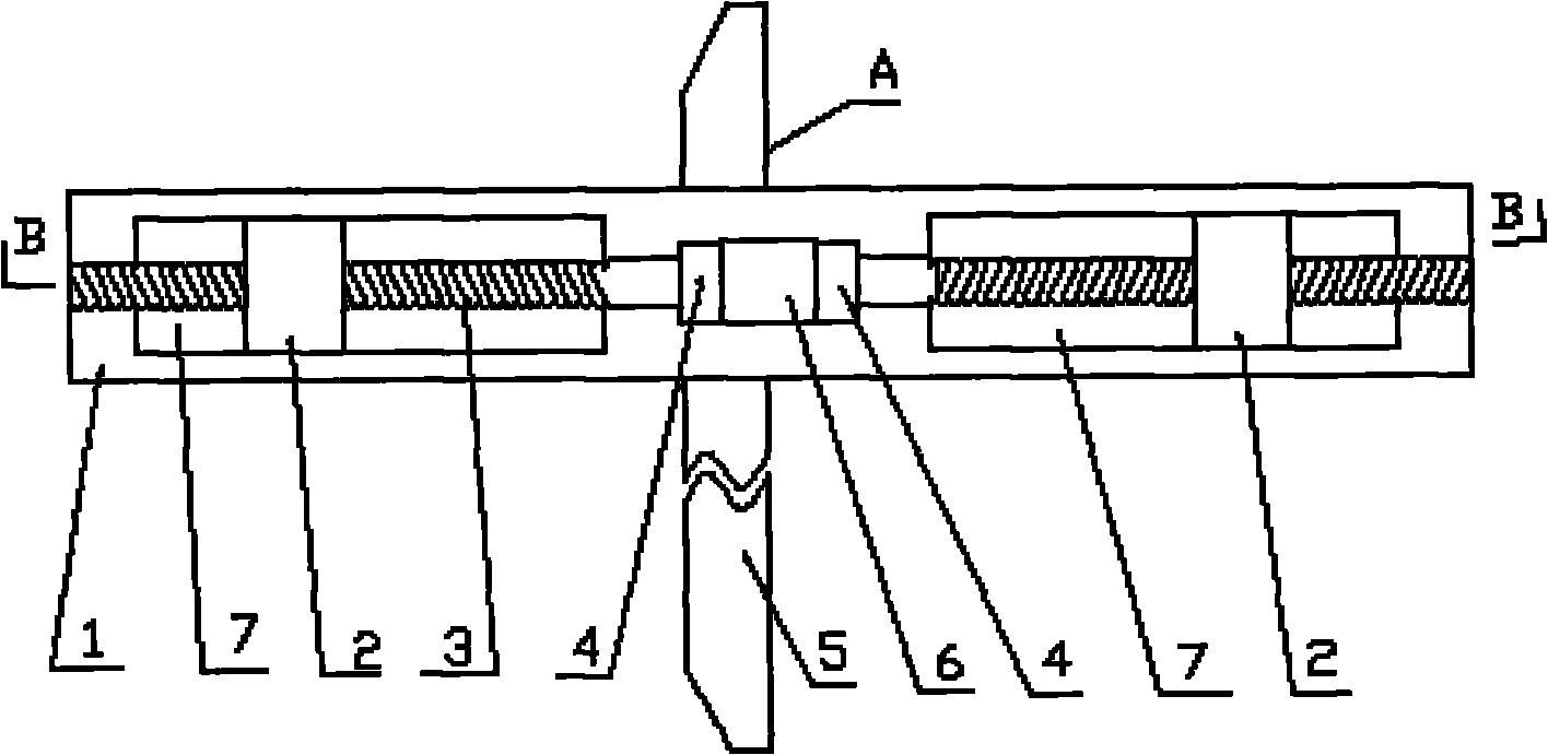
[0010] Produce guide rail (7) symmetrically on both sides of the planning body (1), also make a slide hole perpendicular to the planning body at the middle part of the planning body, install a sliding ruler (5) in the sliding hole, When installing, ensure that the A side of the sliding ruler (5) is always perpendicular to the sides C and D of the ruler body (1), the screw seat (4) is installed and fixed directly above the ruler body (1), and the knob (6) Installed on the screw base (4) through the middle of the screw (3), the connection between the knob (6) and the screw (3) is a fixed connection, and the movable grip (2) is composed of the same two pieces , the movable catch (2) is installed symmetrically on both sides of the lead screw (3) through threaded fit, and at the same time, is installed in the guide rails (7) on both sides of the planning body (1), the lead screw (3) The pitches of the threads at both ends are equal but in opposite directions. Therefore, during the ...


PUM


Abstract

The invention relates to a bisecting and marking gauge. In the invention, guide rails are symmetrically manufactured at two sides of a marking gauge body; a sliding hole vertical to the marking gauge body is manufactured in the middle part of the marking gauge body; a sliding straight scale is arranged in the sliding hole; a face A of the sliding straight scale is vertical to sides C and D of the marking gauge body during installation all the time; a lead screw seat is arranged and fixed right above the marking gauge body; a rotary knob passes through the middle part of a lead screw and is arranged on the lead screw seat; the rotary knob is fixedly connected with the lead screw; movable claws with each composed of two same pieces are symmetrically arranged at two sides of the lead screw in a screw thread fit way and are also arranged in the guide rails at two sides of the marking gauge body; screw threads at two ends of the lead screw have equal screw pitch, but have opposite directions; in the process of rotating the rotary knob, the two movable claws oppositely move; and during the design and the installation; the symmetry is kept between the face A of the sliding straight scale and the two sliding claws all the time.

Description

technical field [0001] The invention relates to a planing plan, in particular to a centering planing plan, which belongs to the technical field of hardware tools. Background technique [0002] In machinery manufacturing and other production fields, it is often encountered that the center of the workpiece is used as the positioning reference process. In order to achieve the requirements of the process, it is necessary to find the center of the workpiece or divide the circle of the workpiece during production. Line drawing, at present, in the field of production, to find out the center of the circle in the workpiece, or divide the circle of the workpiece to draw a line, the general tool used is a compass with a ruler, using the method of geometric line drawing, after many times of drawing In this method, the corresponding points and lines can be found through multiple times of drawing lines, so not only is it more troublesome to use, but also has the disadvantage of low effici...

Claims


Application Information

Patent Timeline
IPC IPC(8): B25H7/04
Inventor 车业好
Owner 车业好
Learn More