Rotary lamp cap

A technology of rotating the lamp head and rotating the ground, which is applied to lighting devices, lighting device parts, lighting auxiliary devices, etc., can solve the problems of high cost, complex structure, unfavorable replacement of light sources, etc., and achieve the effect of convenient change

Active Publication Date: 2011-11-23
ZHAOQING HENGYI INDAL
View PDF5 Cites 15 Cited by
  • Summary
  • Abstract
  • Description
  • Claims
  • Application Information

AI Technical Summary

Problems solved by technology

However, the structure of the existing rotating lamps is complex. In order to rotate the lampshade, the entire lamp including the lampshade needs to be designed as an integral closed
This kind of one-piece closed rotating lamp with complex structure is not only costly, but also not conducive to the replacement of light sources such as light bulbs and lamp tubes, and often requires professional maintenance personnel to complete the replacement of light sources
In addition, when designing the transmission mechanism, the existing rotating luminaires integrate the transmission mechanism and the specific structure of the specific luminaire. For example, one luminaire can only be adapted to one lampshade, resulting in the adaptability and versatility of the luminaire. very poor
[0003] In addition, in the existing rotating device, not only a separate motor is required, but also the output shaft of the motor and the rotation axis of the rotating body need to be staggered from each other.
This results in a complex structure and an excessively large volume of the entire rotating device

Method used


Image

  • Rotary lamp cap
  • Rotary lamp cap
  • Rotary lamp cap

Examples


Embodiment Construction

[0044] Hereinafter, exemplary embodiments of the present invention will be described in detail with reference to the accompanying drawings.

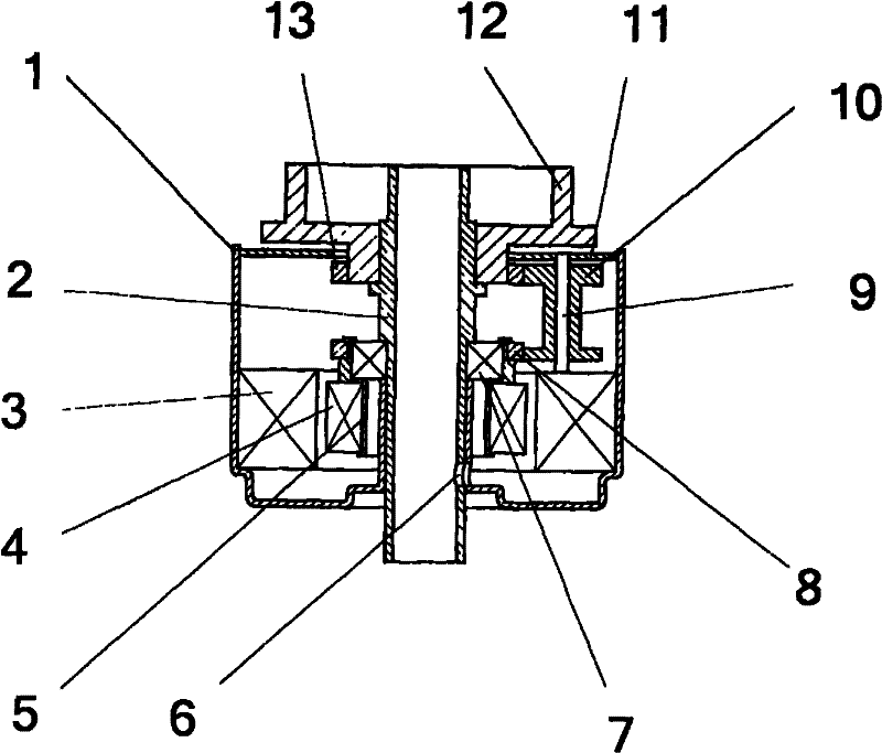
[0045] See figure 1 The rotating lamp cap (or simply called “motor”) according to the first embodiment of the present invention includes a substantially cylindrical or cylindrical housing 1. The housing 1 has a first longitudinal end and an opposite second longitudinal end. The first longitudinal end of the housing 1 is closed by a cover 11. Both the first and second longitudinal ends are provided with a central opening to allow the substantially cylindrical lead post 2 to pass longitudinally.

[0046] The motor stator 3 is provided around the inner peripheral surface of the housing 1. The (hollow) rotating shaft 5 is rotatably mounted around the lead column 2 via a bearing 7. The motor rotor 4 is fixed on the rotating shaft 5 and arranged coaxially with the motor stator 3. The lead post 2 passes through the longitudinal cavity of the rot...


PUM


Abstract

The invention discloses a rotary lamp cap, which comprises a shell, a motor stator, a rotary shaft, a motor rotor, a lamp shade bracket and a speed-reducing transmission system, wherein the shell has a first longitudinal end and a second longitudinal end; the first longitudinal end has an opening; the motor stator is arranged around the surface of the inner circumference of the shell; the rotary shaft is positioned in the shell and rotates relative to the shell; a cavity which is communicated with the opening of the first longitudinal end of the shell is formed in the rotary shaft; the motor rotor is fixed on the rotary shaft and coaxial with the motor stator; the lamp shade bracket rotates relative to the shell and stretches out of the shell; and the speed-reducing transmission system is positioned in the shell and connected with the rotary shaft and the lamp shade bracket respectively. Because the modular rotary lamp cap is small in size and compact in structure and can be completely matched with lamp caps and lamp shades of any standardized form, the rotary lamp cap can completely become a universal substitute for the lamp cap which is arranged on an ordinary lamp.

Description

Technical field [0001] The present invention generally relates to rotating light-emitting objects. More specifically, it relates to a rotating lamp cap (or may be referred to as a "motor") for rotating a light-emitting object such as a rotating lamp. Background technique [0002] The existing rotating lamp usually includes a lampshade that can be rotated so that the lamp has a better visual and display effect and broadens its use range. However, the existing rotating lamp has a complicated structure. In order to rotate the lampshade, the whole lamp including the lampshade needs to be designed as an integrated closed type. This kind of integrated enclosed rotary lamp with a complicated structure is not only costly, but also not conducive to replacing light sources such as bulbs and tubes, and often requires professional maintenance personnel to complete the replacement of the light source. In addition, when designing the transmission mechanism, the existing rotating luminaires a...

Claims


Application Information

Patent Timeline
Patent Type & Authority Applications(China)
IPC IPC(8): F21V21/00
Inventor 李良清王晓冰
Owner ZHAOQING HENGYI INDAL
Why Eureka
Try Eureka