
Wheel speed sensor testing machine

A wheel speed sensor and testing machine technology, which is used in the testing/calibration of speed/acceleration/shock measurement equipment, speed/acceleration/shock measurement, instruments, etc., and can solve problems such as inconvenient operation and complex structure

Inactive Publication Date: 2011-12-14
鼎佳(天津)汽车电子有限公司
View PDF1 Cites 11 Cited by
  • Summary
  • Abstract
  • Description
  • Claims
  • Application Information

AI Technical Summary

Problems solved by technology

The probes of the wheel speed sensor are installed on the outer side of the ring gear installed on the wheel at intervals. When the peaks and valleys of the teeth on the ring gear pass through the wheel speed sensor, the magnetic field strength changes, and the induced voltage is proportional to the rotation speed of the wheel. After conversion by the ECU, it is obtained The number of revolutions of the wheels, the ECU repeatedly reduces or increases the brake pressure on the wheels to control the slippage rate of the wheels according to the current speed. It can be seen that the normal operation of the wheel speed sensor is directly related to the safety of the vehicle. The quality of the current wheel speed sensor The detection device has a complex structure and is inconvenient to operate

Method used


Image

  • Wheel speed sensor testing machine
  • Wheel speed sensor testing machine
  • Wheel speed sensor testing machine

Examples


Embodiment Construction

[0011] Below in conjunction with the examples, the present invention is further described, the following examples are illustrative, not limiting, and the protection scope of the present invention cannot be limited by the following examples.

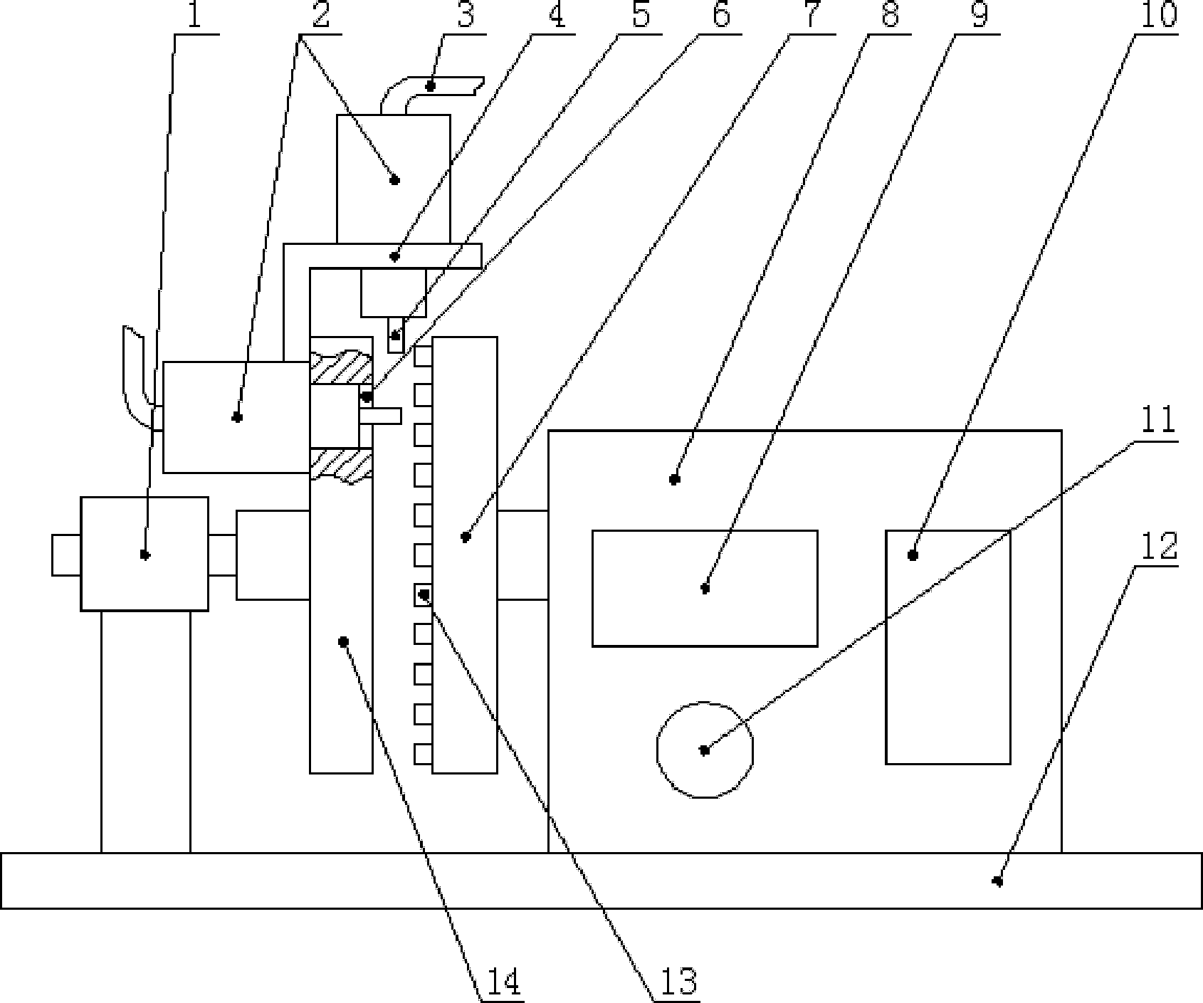
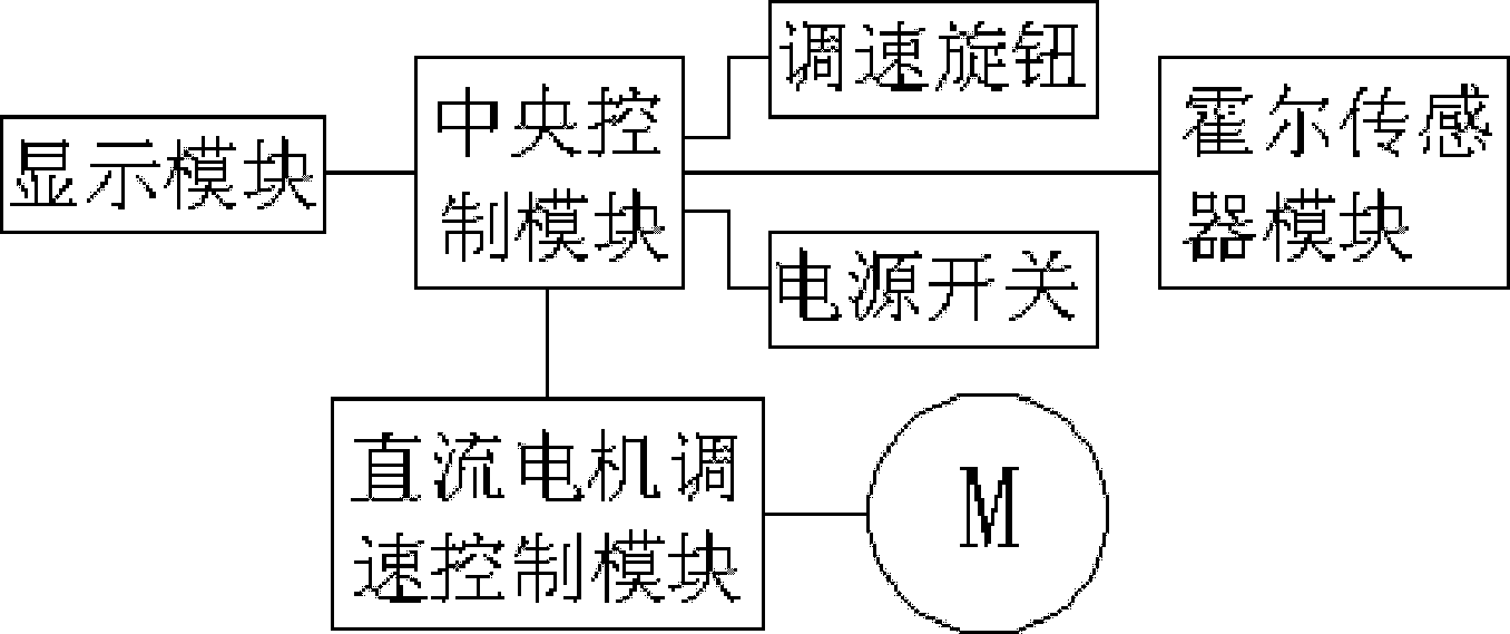
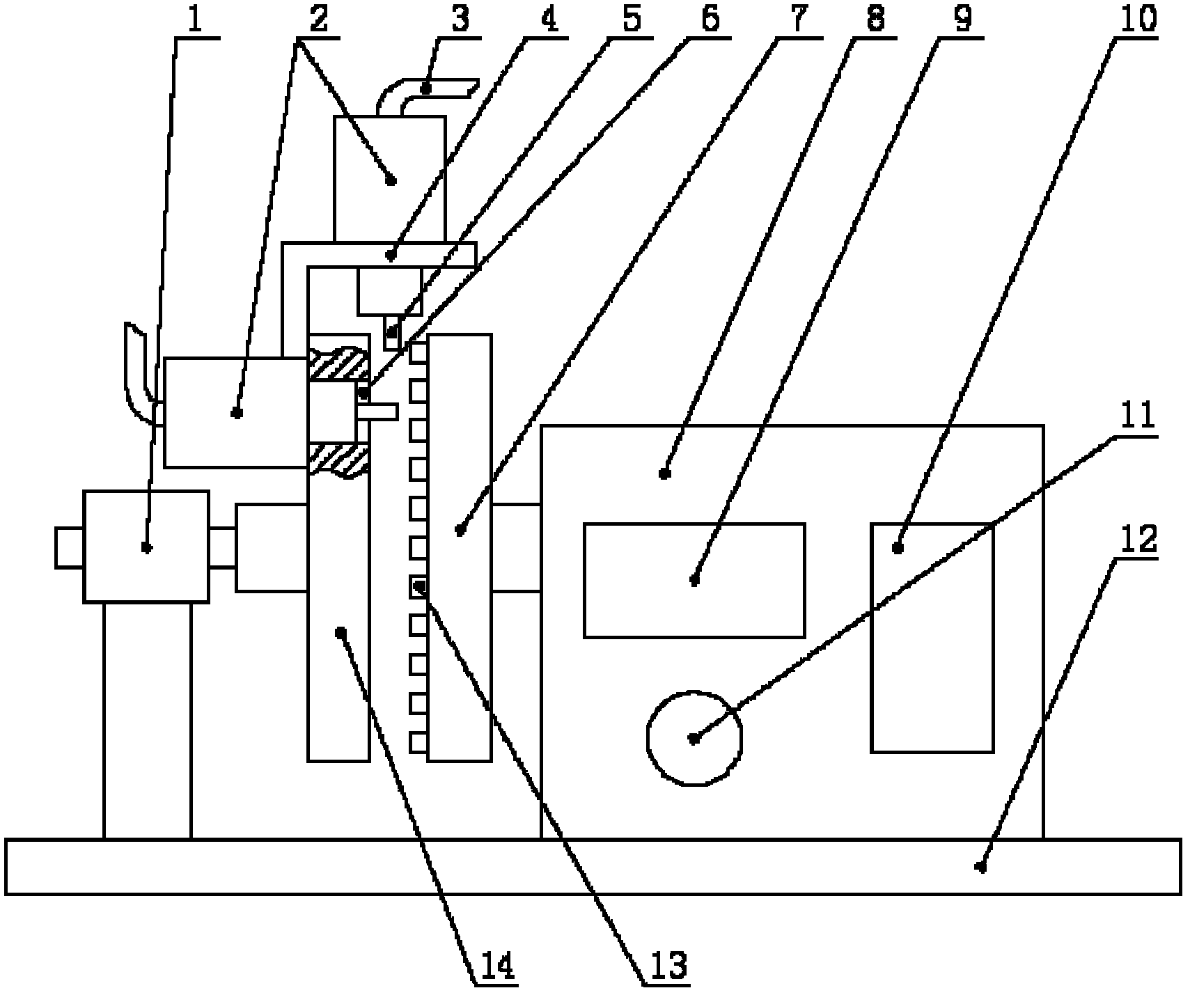
[0012] A wheel speed sensor testing machine, such as Figure 1~2 As shown, it includes a base 12, a casing 8, a DC motor M, a ring gear 7 and a wheel speed sensor mounting frame. The wheel speed sensor mounting frame is composed of a disc 14 and a connecting plate 4. The shell is installed on the base, and the DC motor M is installed in the shell. , the DC motor M protrudes out of the shell on the output shaft and installs the ring gear coaxially, and installs the mounting column 1 on the base outside the outer end surface of the ring gear. The through hole 6 for clamping the wheel speed sensor 2 is formed on the connecting plate, and the display module 9 and the speed control knob 11 are embedded on the shell. The display module and the ...


PUM


Abstract

The invention relates to a wheel speed sensor testing machine, which is characterized in that it comprises a base, a casing, a DC motor, a ring gear and a wheel speed sensor mounting frame. When the present invention is used, the wheel speed sensor is vertically or horizontally clamped on the wheel speed sensor mounting frame, so that the probe of the wheel speed sensor is close to the ring gear, and when the DC motor drives the ring gear to rotate, the induced voltage generated by the wheel speed sensor Inputting it into the oscilloscope, the tester can easily check the working condition of the wheel speed sensor, and the tester can adjust the speed of the DC motor through the speed control knob to detect the wheel speed sensor, which is very convenient.

Description

technical field [0001] The invention relates to the technical field of wheel speed sensors, in particular to a wheel speed sensor testing machine. Background technique [0002] In the ABS system of the vehicle, the wheel speed sensor transmits the speed signal of the wheel to the ECU, and the ECU calculates and obtains the current rotation speed of the wheel. The probes of the wheel speed sensor are installed on the outer side of the ring gear installed on the wheel at intervals. When the tooth peaks and tooth valleys on the ring gear pass through the wheel speed sensor, the magnetic field strength changes, and the induced voltage is proportional to the wheel speed. After conversion by the ECU, the The number of revolutions of the wheels, the ECU repeatedly reduces or increases the brake pressure on the wheels to control the slippage rate of the wheels according to the current speed. It can be seen that the normal operation of the wheel speed sensor is directly related to th...

Claims


Application Information

Patent Timeline
Patent Type & Authority Applications(China)
IPC IPC(8): G01P21/02
Inventor 张凤洪
Owner 鼎佳(天津)汽车电子有限公司
Learn More