Clip-on led flood light

A LED floodlight, clamping technology, applied in the field of clamping LED floodlights, can solve the problems that LED floodlights are difficult to realize

Inactive Publication Date: 2011-12-21
SUZHOU JINGLEI PHOTOELECTRIC LIGHTING TECH
View PDF3 Cites 1 Cited by
  • Summary
  • Abstract
  • Description
  • Claims
  • Application Information

AI Technical Summary

Problems solved by technology

In lighting applications, it is often necessary to install LED floodlights on plate-shaped protrusions, and the plate-shaped protrusions may protrude vertically or horizontally, especially if the

Method used


Image

  • Clip-on led flood light
  • Clip-on led flood light

Examples


Embodiment Construction

[0012] The present invention will be further described below in conjunction with the accompanying drawings.

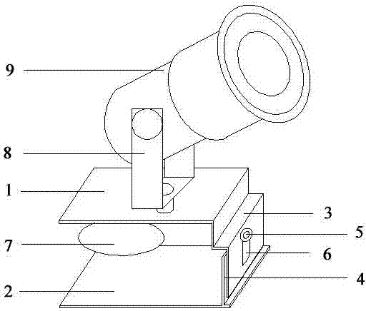
[0013] Such as figure 1 As shown, the base of the clip-on LED floodlight is composed of a fixed upper plate 1, a fixed lower plate 2, a first connecting plate 3, a second connecting plate 4 and a tension adjustment knob 5, wherein the fixed upper plate 1 is connected to the first The plate 3 is integrally formed, the fixed lower plate 2 and the second connecting plate 4 are integrally formed, and the tension adjustment knob 5 passes through the hollow slide rail 6 on the first connecting plate 3 and the second connecting plate 4 and the first connecting plate 3 is connected with the second connection plate 4, the lower end surface of the fixed upper plate 1 is provided with a suction cup 7, the upper part of the fixed upper plate 1 is provided with an adjustable "U"-shaped bracket 8, and the adjustable "U"-shaped bracket 8 is connected with the LED projection Light la...


PUM


Abstract

The invention discloses a clip-type LED projection lamp, which includes a lamp body and a base of the LED projection lamp, and is characterized in that: the lamp body of the LED projection lamp is connected to the base through an adjustable "U"-shaped bracket, and the The base is composed of a fixed upper plate, a fixed lower plate and a connecting portion, and the fixed upper plate and the fixed lower plate are connected through the connecting portion to form a semi-enclosed frame base. The invention is mainly used for projection lighting, has a simple structure, can adjust the projection angle of the LED projection lamp, and is especially suitable for clamping and fixing on a plate-shaped protrusion.

Description

technical field [0001] The invention relates to a lighting device, in particular to a clip-type LED floodlight. Background technique [0002] In recent years, the cost of LED consumables for lighting has been gradually reduced, and its performance has been further developed. Compared with traditional light sources, it has advantages in service life, start-up time, stability, safety, and environmental protection. Therefore, it is widely used and used in individual In the field of lighting, it completely replaces the traditional light source. [0003] With the development and progress of high-power LED technology, more and more LED floodlights have been used in various lighting fields. Traditional LED floodlights are mainly composed of lamp body and base, and are equipped with simple adjustment device and heat sink. In lighting applications, it is often necessary to install LED floodlights on plate-shaped protrusions, and the plate-shaped protrusions may protrude vertically ...

Claims


Application Information

Patent Timeline
IPC IPC(8): F21S8/00F21V21/14F21Y101/02
Inventor 董春保
Owner SUZHOU JINGLEI PHOTOELECTRIC LIGHTING TECH
Why Eureka
Try Eureka