Side-hung type project lamp

A floodlight and side-mounted technology, applied in the field of side-mounted floodlights, can solve the problem of single installation of floodlights and achieve good heat dissipation

Inactive Publication Date: 2016-04-13
CHONGQING BEACON OPTOELECTRONICS TECH
View PDF0 Cites 0 Cited by
  • Summary
  • Abstract
  • Description
  • Claims
  • Application Information

AI Technical Summary

Problems solved by technology

[0002] Floodlights are lamps whose illuminance on the specified illuminated surface is higher than that of the surrounding environment, also known as spotlights. Usually, they can aim at the required direction and require a structure that is not affected by climatic conditions. They are mainly used in large-scale operation sites, mines, Building outlines, stadiums, overpasses, parks and flower beds, etc. Therefore, almost all large-area lighting fixtures used outdoors can be regarded as floodlights. The beam angle of the floodlights can be wide or narrow, and the range of variation is 5°-110° °Between, more and more cities are beginning to install corresponding floodlights for night lighting in blocks with relatively concentrated high-rise buildings, bustling business districts or urban landmark buildings, so as to brighten and beautify the city at night. As a result, floodlights have been developed rapidly. The structure of a typical floodlight includes a lamp housing, a light source assembly and a ballast arranged in the lamp housing, and the fixing method of the lamp housing and the bracket determines the lamp housing. The current installation method of floodlights is single, and generally adopts sitting installation, but in some special occasions, it is necessary to change the floodlights to hanging installation. At present, there is no floodlight that can meet this installation requirement on the market. lamp

Method used


Image

  • Side-hung type project lamp
  • Side-hung type project lamp
  • Side-hung type project lamp

Examples


Embodiment Construction

[0020] The present invention will be further described below in conjunction with the embodiments and accompanying drawings.

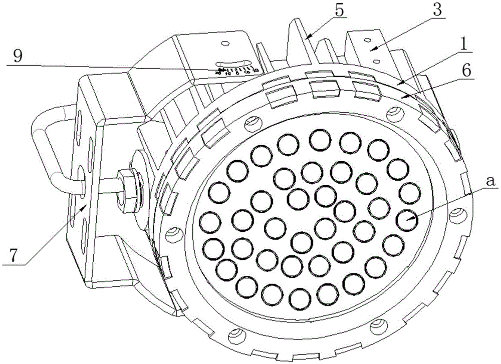
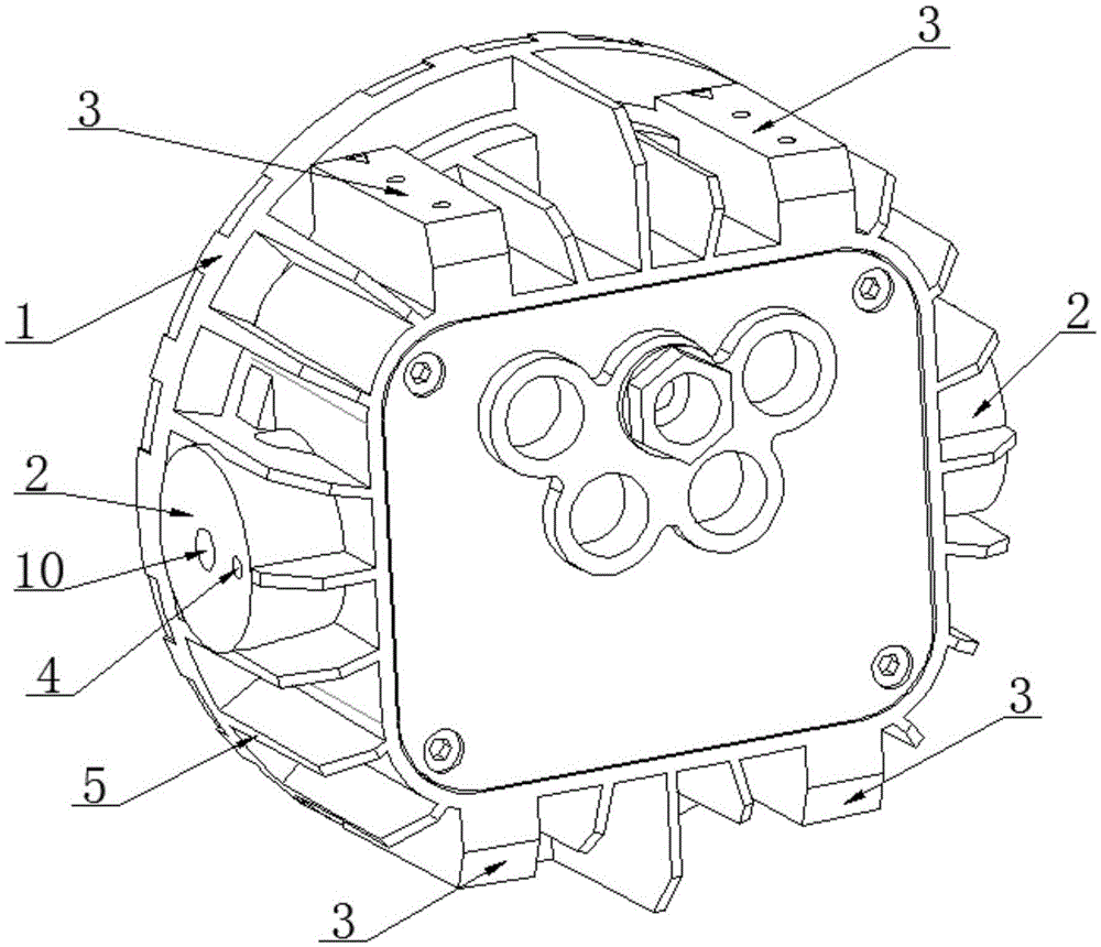
[0021] Such as Figure 1-5 As shown, a side-mounted floodlight includes a lamp housing 1, a lamp body a is arranged inside the lamp housing 1, a lamp housing cover 6 is fastened on the lamp housing 1, and the lamp housing 1 A lamp body hanger 7 is arranged on it, and heat dissipation fins 5 are evenly arranged on the outer surface of the lamp housing 1 along the circumferential direction.

[0022] The lamp body a includes a light source assembly a5, on which a lens assembly a4, a pressure plate a3, and a glass a2 are sequentially arranged, and a waterproof rubber ring a1 is arranged between the glass a2 and the lamp housing cover 6 .

[0023] On the outer surface of the lamp housing 1, there are seat-type installation bases 2 and hanging-type installation bases 3. There are two seat-type installation bases 2, and the seat-type installation bases 2 are...


PUM


Abstract

The invention discloses a side-hung type project lamp which comprises a lamp housing. A lamp body is arranged in the lamp housing. A lamp housing surface cover is buckled to the lamp housing in a covering manner. A lamp body hanger is arranged on the lamp housing. The lamp body comprises a light source assembly. The light source assembly is sequentially provided with a lens assembly, a pressing plate and glass. A waterproof rubber gasket is arranged between the glass and the lamp housing surface cover. Seat type mounting bases and a hanging type mounting base are annularly arranged on the outer surface of the lamp housing. The number of the seat type mounting bases is two. The portion, between the two seat type mounting bases, of the lamp housing is provided with the hanging type mounting base. The lamp body hanger is fixedly arranged on the hanging type mounting base. The lamp body hanger is mounted on the lamp housing in a side-hung manner. The lamp body hanger arranged in the side-hung manner can be demounted and then mounted on the seat type mounting bases according to the requirements, the mounting manner is changed into the seat type mounting manner, and the multiple mounting manners can meet different mounting requirements of different occasions.

Description

technical field [0001] The invention relates to a lighting device, in particular to a side-mounted floodlight. Background technique [0002] Floodlights are lamps whose illuminance on the specified illuminated surface is higher than that of the surrounding environment, also known as spotlights. Usually, they can aim at the required direction and require a structure that is not affected by climatic conditions. They are mainly used in large-scale operation sites, mines, Building outlines, stadiums, overpasses, parks and flower beds, etc. Therefore, almost all large-area lighting fixtures used outdoors can be regarded as floodlights. The beam angle of the floodlights can be wide or narrow, and the range of variation is 5°-110° °Between, more and more cities are beginning to install corresponding floodlights for night lighting in blocks with relatively concentrated high-rise buildings, bustling business districts or urban landmark buildings, so as to brighten and beautify the ci...

Claims


Application Information

Patent Timeline
Patent Type & Authority Applications(China)
IPC IPC(8): F21S8/00F21V21/14
CPCF21S8/036F21V21/14
Inventor 邵群
Owner CHONGQING BEACON OPTOELECTRONICS TECH
Why Eureka
Try Eureka