constant voltage regulator

A technology of constant pressure regulator and throttle valve, which is applied to safety valves, engine components, balance valves, etc., can solve the problems of high cost, large volume and difficult modification, and achieve the effect of preventing blocking phenomenon.

Inactive Publication Date: 2011-12-28
李耀强
View PDF6 Cites 16 Cited by
  • Summary
  • Abstract
  • Description
  • Claims
  • Application Information

AI Technical Summary

Problems solved by technology

But there are two disadvantages. One is that the volume is larger and the cost is higher. The other is that in practical applications, when the installation of the water supply system has been completed, the water pipe joints of some water outlets are buried in the wall, so it is very difficult to refit. up

Method used


Image

  • constant voltage regulator
  • constant voltage regulator
  • constant voltage regulator

Examples


Embodiment Construction

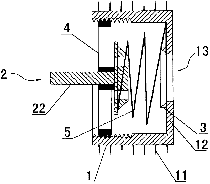
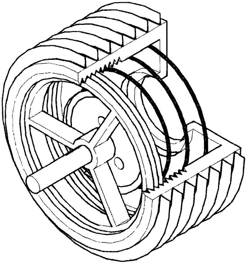
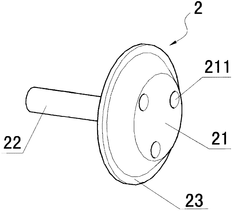
[0023] Such as figure 1 , figure 2 , image 3 , Figure 4 As shown, the constant pressure stabilizer is mainly composed of a base 1, a throttle valve 2, a conical table 3, a positioning seat 4, and a spring 5. The throttle valve 2 includes a conical body 21, a valve stem 22 and a protrusion Edge 23, the base 1 is made of plastic, the outer wall is provided with a sealing pleat 11, the outlet end of the base 1 is provided with a platform 12, and a hole 13 is provided in the center of the platform 12; the spring 5 adopts a tower structure, the large-diameter end is placed on the platform 12 in the base 1; the center hole of the positioning seat 4 is sleeved on the valve stem 22, and the positioning seat 4 enters from the inlet end of the base 1, and is screwed on the base 1 of the inner wall.

[0024] The outer wall of the positioning seat 4 is provided with threads that match the inner wall of the base 1.

[0025] The flange 23 is provided on the bottom edge of the cone 21; the d...


PUM


Abstract

The constant pressure current stabilizer is mainly composed of a base, a throttle valve, a conical platform, a positioning seat, and a spring. The outlet end of the base is provided with a platform, and a hole is provided in the center of the platform; the spring It adopts a tower structure, the large-diameter end is placed on the platform in the base, the small-diameter end is sleeved on the outer edge of the cone and pressed on the flange; the center hole of the positioning seat is sleeved on the valve stem, and the positioning seat The outer wall is provided with a thread that matches the inner wall of the base, and the positioning seat is screwed on the inner wall of the base, and the prestressed pressure of the spring can be adjusted by adjusting the position of the positioning seat on the inner wall of the base, so as to achieve the purpose of stabilizing the voltage and controlling the flow .

Description

Technical field [0001] The invention relates to a constant pressure stabilizer capable of automatically adjusting water pressure and air pressure, in particular to the adjustment of water pressure, which belongs to the technology of automatic pressure adjustment. Background technique [0002] In the existing liquid or gas delivery systems, most of the connections between the ends and specific appliances do not have pressure adjustment devices. Such as the connection of the faucet and the water pipe, the connection of the air pump and the pneumatic nail gun, etc. [0003] Take tap water as an example. The connection between tap water pipes and the connection between water pipes and faucets are all realized through joints. At present, these connectors are mainly used for connection and do not have other functions. At present, there are generally two ways to supply water in buildings. One is to use a booster pump to deliver water from the bottom up, and the other is to place a water...

Claims


Application Information

Patent Timeline
Patent Type & Authority Applications(China)
IPC IPC(8): F16K17/30
Inventor 李耀强
Owner 李耀强
Why Eureka
Try Eureka