
Trimming die structure for mobile phone casing

A technology for trimming molds and casings, which is applied in the field of molds in machining, can solve problems such as reducing production efficiency, increasing manpower and material resources, and increasing production costs, and achieves the effect of ensuring the effect of use.

Inactive Publication Date: 2012-01-04
上海隆江医疗器械有限公司
View PDF7 Cites 19 Cited by
  • Summary
  • Abstract
  • Description
  • Claims
  • Application Information

AI Technical Summary

Problems solved by technology

[0002] Mobile phones are commonly used electronic products in people's daily life. Mobile phone shells are generally made of metal materials such as stainless steel. The current method of forming metal materials is to use stamping dies to form metal materials according to the stamping process. Mobile phone shell products are due to The precision requirements are relatively high. During the entire assembly process of the mobile phone, since each component is installed inside the mobile phone shell, the assembly accuracy requirements between each component are very high, especially the electronic products installed in the mobile phone shell are very sensitive, so the The burrs generated during the stamping process of the mobile phone case need to be removed through the follow-up process. Since the general enterprise uses a punch to cut the semi-finished mobile phone case from the outside to the inside when making the mobile phone case, this processing method causes burrs to be generated in the assembly of the mobile phone case. On the one hand, this will greatly affect the sensitivity of sensitive mobile phones, and the process of removing burrs from metal products using single-process molds through subsequent processes is too complicated and requires the use of multiple sets of metal stamping dies, which increases the Manpower and material resources, and because of the need for multiple positioning, the stability is not high, which increases the production cost and reduces the production efficiency. It will also increase the scrap rate of the product and increase the difficulty of cost control of production.

Method used


Image

  • Trimming die structure for mobile phone casing
  • Trimming die structure for mobile phone casing
  • Trimming die structure for mobile phone casing

Examples


Embodiment Construction

[0013] The present invention will be further described below in conjunction with specific embodiments and accompanying drawings.

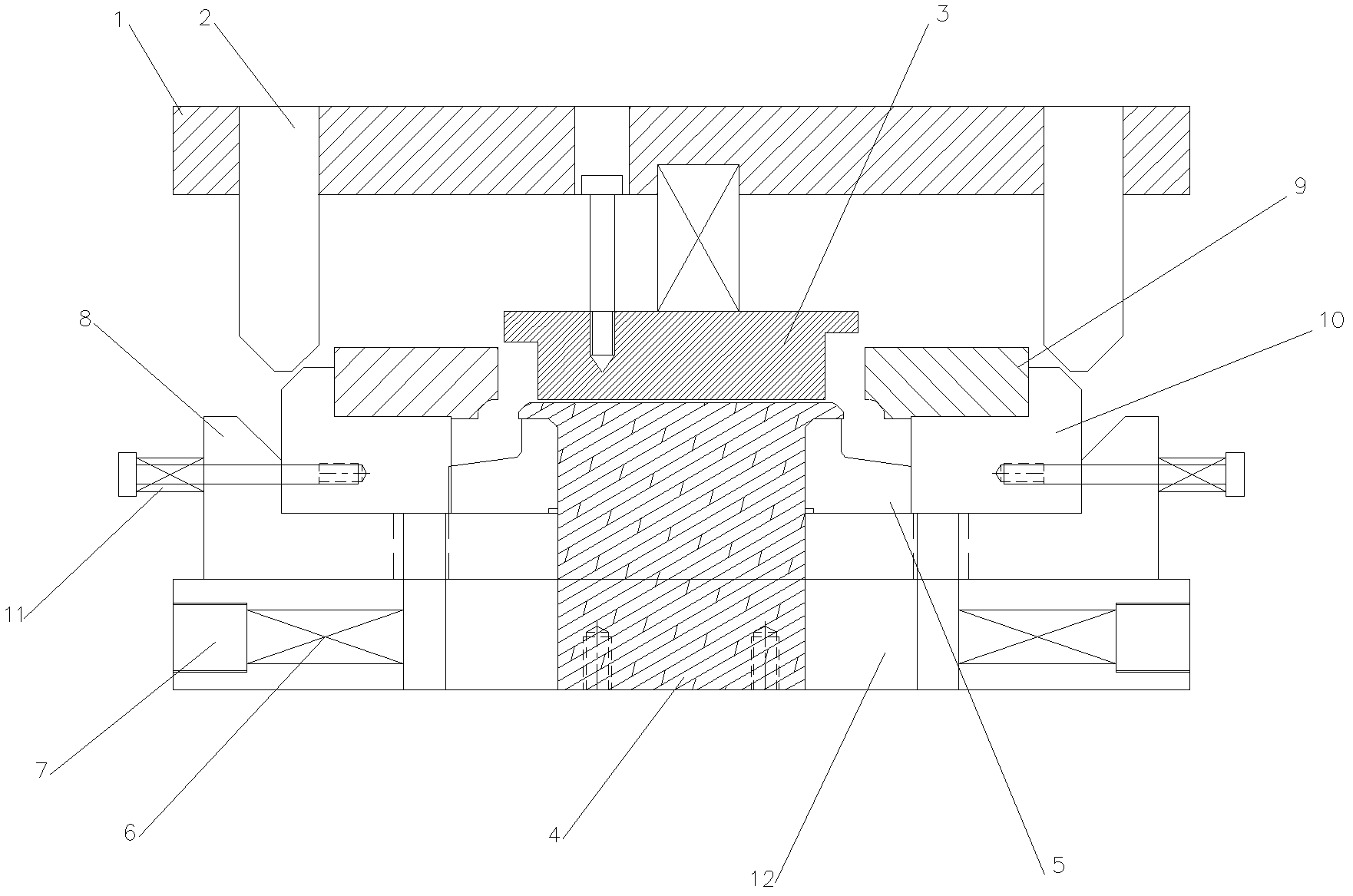
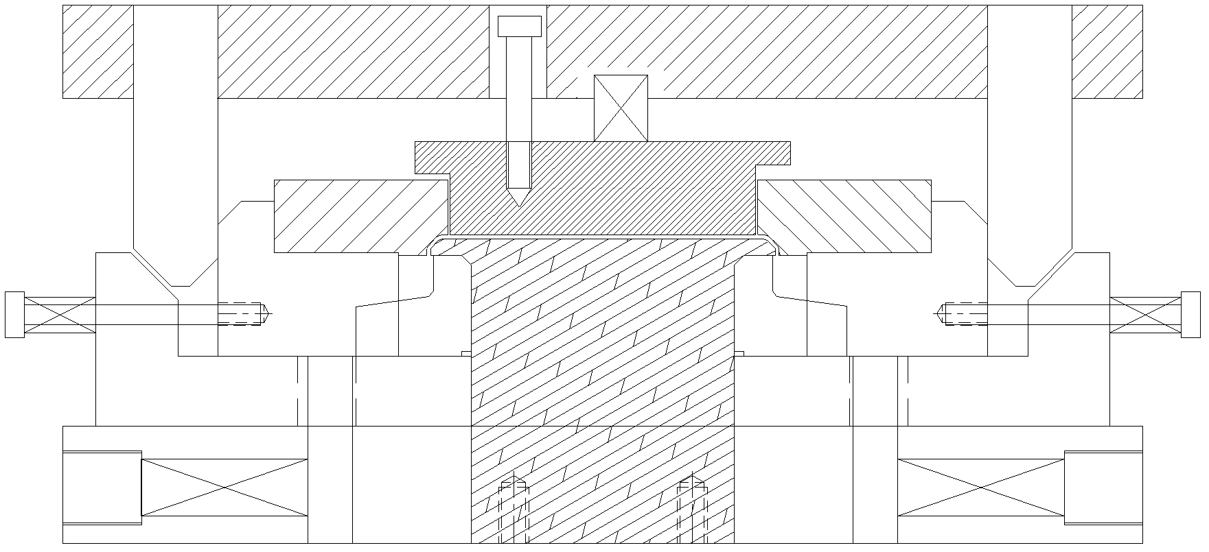
[0014] as attached figure 1 As shown, a mobile phone casing edge trimming mold structure, which includes an upper mold part and a lower mold part, wherein the upper mold part includes an upper splint 1, a bevel 2, and a stripper plate 3, and the lower mold part includes a product positioning core 4. Punch cutter 5, punch cutter 6, punch reset screw 7, punch cutter slider 8, die cutter 9, die cutter slider 10, die cutter slider The return spring 11, the lower mold base 12, the bevel 2 are installed on the upper splint 1, the stripper plate 3 is installed on the upper splint 1 through the unloading screw, the product positioning core 4 is fixed on the lower mold base 12, and the punch cutter The slider 8 is installed on the upper surface of the lower die base 12, the die cutter slider 10 is installed in the punch cutter slider 8, and the punch cutte...


PUM


Abstract

The invention provides a trimming die structure for a mobile phone casing. The structure comprises an upper die part and a lower die part, and is characterized in that: the upper die part comprises an upper splint, a slanted wedge and a stripper plate; and the lower die part comprises a product positioning die core, a male die cutter, a male die return spring, a male die return stop screw, a maledie cutter slide block, a female die cutter, a female die cutter slide block, a female die cutter slide block return spring and a lower die holder. By the trimming die structure for the mobile phone casing, the mobile phone casing is punched from inside to outside by a punching head, so that burrs are generated on the outer surface of the mobile phone casing, assembly of electronic parts of a mobile phone is not influenced, and the use effect of the mobile phone is ensured.

Description

technical field [0001] The invention relates to a mold in mechanical processing, in particular to a mobile phone case trimming mold structure. Background technique [0002] Mobile phones are commonly used electronic products in people's daily life. Mobile phone shells are generally made of metal materials such as stainless steel. The current method of forming metal materials is to use stamping dies to form metal materials according to the stamping process. Mobile phone shell products are due to The precision requirements are relatively high. During the entire assembly process of the mobile phone, since each component is installed inside the mobile phone shell, the assembly accuracy requirements between each component are very high, especially the electronic products installed in the mobile phone shell are very sensitive, so the The burrs generated during the stamping process of the mobile phone case need to be removed through the follow-up process. Since the general enterpri...

Claims


Application Information

Patent Timeline
IPC IPC(8): B21D28/14
Inventor 张依平侯斌平
Owner 上海隆江医疗器械有限公司
Learn More