Wire discharging frame

A pay-off frame and body part technology, applied in the field of pay-off racks, can solve problems such as messy threads, increased production costs, and different normal production, and achieve the effect of ensuring pay-off

Active Publication Date: 2012-01-04
ZHANGJIAGANG HENGCHANG WELDING MATERIALS
View PDF5 Cites 5 Cited by
  • Summary
  • Abstract
  • Description
  • Claims
  • Application Information

AI Technical Summary

Problems solved by technology

[0002] There are generally two ways to pay off the steel wire rod during wire drawing: the first way is: the steel wire rod is directly laid flat on the ground, and the wire end of the wire rod is pulled out and led to the coil pulley of the wire drawing machine. The wire method needs a special person to monitor the steel wire rod pay-off status, because it is very easy for multiple coils of wire rods to be pulled out at the same time and twisted and broken, which will eventually be different from normal production. Large potential safety hazards involved; the second method: place the steel wire rod vertically on the ground or on the pay-off rack, pull the wire end out through a bell-shaped retaining coil, and then lead it to the wire drawing machine to realize wire drawing. Because this method needs to turn the steel wire rod vertically, it even needs a special machine to stand it up, which increases the production cost. In addition, it is also prone to messy wires and multiple windings, which cannot guarantee normal and smooth pay-off

Method used


Image

  • Wire discharging frame
  • Wire discharging frame
  • Wire discharging frame

Examples


Embodiment Construction

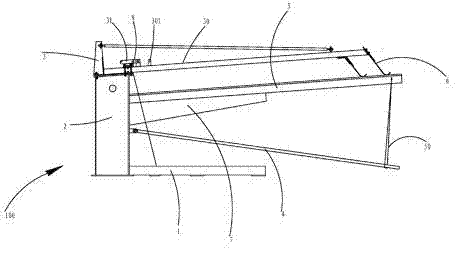
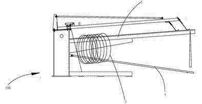
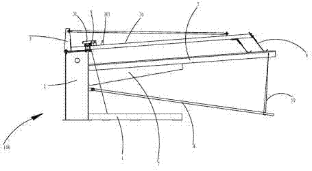
[0009] see figure 1 and figure 2 , a pay-off stand 100, the pay-off stand 100 includes a machine base 1, a body part 2 protruding from the machine base 1, a rotating part 3 and a screw rod 4 installed on the main body part 2, the rotating part 3 And the screw rod 4 can rotate relative to the body part 2, the body part 2 protrudes with a hanging rod 5 integrally formed with the body part 2, the rotating part 3 is arranged in a triangle and is provided with a mounting rod 30, the Two shrapnels 6 are installed on the front end of the mounting rod 30 . The elastic piece 6 is mounted on the front end of the mounting rod 30 through a fixing member. A supporting rib 7 is provided between the hanging rod 5 and the main body 2 , so as to enhance the structural strength between the hanging rod 5 and the main body 2 . A chain 50 is installed on the hanging rod 5, and when the steel wire rod 9 needs to be loaded on the pay-off frame 100, the chain 50 is encased on the screw rod 4, so ...


PUM


Abstract

The invention discloses a wire discharging frame. The wire discharging frame comprises a base, a body part which protrudes from the base, and a rotating part and a thread pressing rod which are arranged on the body part, wherein the rotating part and the thread pressing rod can rotate relative to the body part; a hanging rod which is integrated with the body part protrudes from the body part; the rotating part is provided with an installation rod; and at least one elastic piece is arranged at the front end of the installation rod. By using the wire discharging frame, a steel wire rod can be naturally loosened after a binding belt is opened, and due to the elastic piece, the wire rod can only be sprung one circle by one circle, so that the phenomenon that a plurality of circles are twisted is avoided, and a wire can be discharged smoothly.

Description

technical field [0001] The invention relates to the field of pay-off devices, in particular to a pay-off frame. Background technique [0002] There are generally two ways to pay off the steel wire rod during wire drawing: the first way is: the steel wire rod is directly laid flat on the ground, and the wire end of the wire rod is pulled out and led to the coil pulley of the wire drawing machine. The wire method needs a special person to monitor the steel wire rod pay-off status, because it is very easy for multiple coils of wire rods to be pulled out at the same time and twisted and broken, which will eventually be different from normal production. Large potential safety hazards involved; the second method: place the steel wire rod vertically on the ground or on the pay-off rack, pull the wire end out through a bell-shaped retaining coil, and then lead it to the wire drawing machine to realize wire drawing. Because this method needs to flip the steel wire rod vertically, it...

Claims


Application Information

Patent Timeline
Patent Type & Authority Applications(China)
IPC IPC(8): B65H49/04
Inventor 罗国平
Owner ZHANGJIAGANG HENGCHANG WELDING MATERIALS
Why Eureka
Try Eureka