Spiral rocker guide rod composite hinge groove cam combination space mechanism for sliding-plug door

A compound hinge and guide rod technology, which is applied in the direction of power control mechanism, wing leaf control mechanism, door device, etc., can solve the problems of affecting the dynamic stability of the door leaf, the poor stability of the main shaft, and the large space occupied, etc., and achieve the plug seal Rapid reliability, increased rigidity, and low friction and wear

Active Publication Date: 2014-05-28
海宁市袁花镇工业投资有限公司
View PDF2 Cites 0 Cited by
  • Summary
  • Abstract
  • Description
  • Claims
  • Application Information

AI Technical Summary

Problems solved by technology

[0004] 1) The A-type plug door of the domestic A company realizes the opening and closing of the door along the x direction, and realizes the plug movement along the y direction to achieve sealing, but the main axis moving along the x direction is not fixed, it moves along the y direction at the same time, Therefore, the stability of the spindle is slightly poor, the structure size is large, and the space occupied is large;
[0005] 2) The B-type sliding door of foreign company B realizes the opening and closing of the door along the x direction. The main shaft moving in the x direction is fixed and has good rigidity. The rod mechanism realizes the plugging of the door, and its rigidity is good, but the structural size is large, and the door leaf has a swing up and down when it is used as a plug, which will affect the dynamic stability of the door leaf when it is quickly opened and closed;
[0006] 3) The C-type plug door of foreign C company also realizes the door opening and closing along the x direction, the main shaft is fixed, and the plug movement of the door is realized by a four-bar mechanism that rotates around the z axis, and its rigidity is good. However, when the door leaf is used as a plug, the support must be strengthened along the z-axis direction, which makes the structural size larger and the cost higher

Method used


Image

  • Spiral rocker guide rod composite hinge groove cam combination space mechanism for sliding-plug door
  • Spiral rocker guide rod composite hinge groove cam combination space mechanism for sliding-plug door
  • Spiral rocker guide rod composite hinge groove cam combination space mechanism for sliding-plug door

Examples


Embodiment Construction

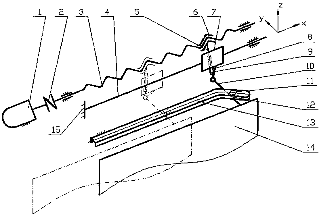
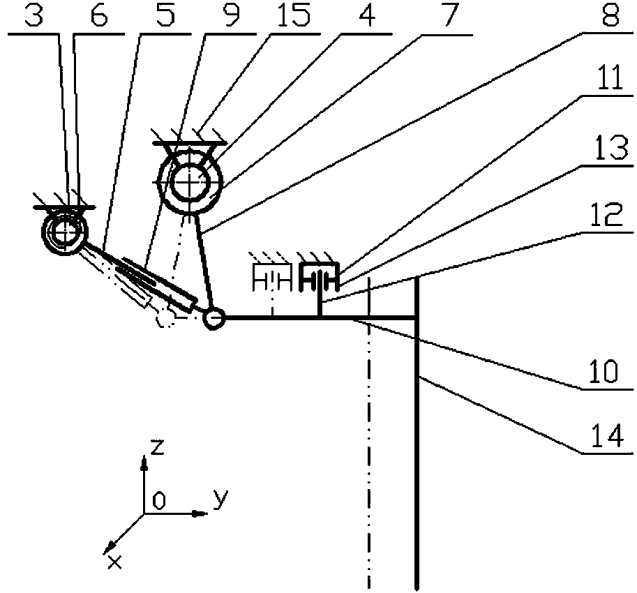
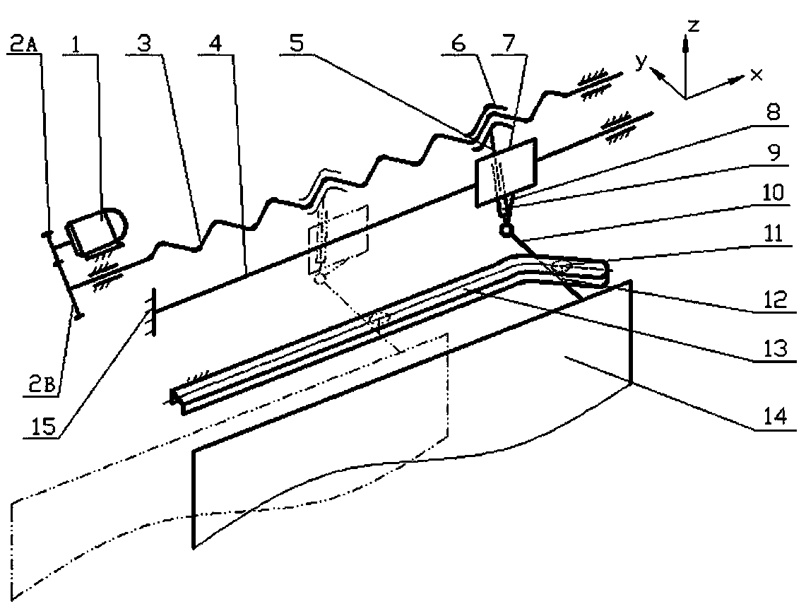
[0025] Reference attached Figure 1~4 , A sliding plug door screw rocker guide rod compound hinge groove cam combined space mechanism of the present invention includes a motor 1, a coupling 2, a screw rod 3, a bearing shaft 4, a guide rod 5, a nut 6, a shaft sleeve 7, and a carrying door Rocker (referred to as rocker) 8, guide rod sleeve 9, door handle 10, roller 11, roller shaft 12, groove cam 13, door leaf 14 and door frame 15, which consist of screw 3, nut 6, and door frame 15 Screw mechanism; the guide rod 5 and the nut 6 are solidly integrated, the guide rod 5, the rocker 8, the guide rod sleeve 9, the shaft sleeve 7, and the bearing shaft 4 constitute a rocker guide rod mechanism; the bearing shaft 4, the rocker 8 and It forms a groove cam mechanism with roller 11, roller shaft 12, groove cam 13, door handle 10, door leaf 14, and door frame 15; guide rod sleeve 9, rocker 8 and door handle 10 form a composite hinge. The mechanism, the rocker guide rod mechanism and the gr...


PUM


Abstract

The invention discloses a spiral rocker guide rod composite hinge groove cam combination space mechanism for a sliding-plug door, relates to a sliding and plug, sealing, and opening and closing mechanism for the sliding-plug door for a vehicle, in particular to the spiral rocker guide rod composite hinge groove cam combination space mechanism for the sliding-plug door for high-speed rail or other railway vehicles. The mechanism comprises a motor, a coupler, a screw, a bearing shaft, a guide rod, a nut, a shaft sleeve, a door carrying rocker, a guide rod sleeve, a door handle, a roller, a roller shaft, a groove cam, a door leaf and a door frame; a spiral mechanism consists of the screw, the nut and the door frame; the guide rod and the nut which are fixedly integrated, a rocker guide rod mechanism consists of the guide rod, the rocker, the guide rod sleeve, the shaft sleeve and the bearing shaft; a groove cam mechanism consists of the bearing shaft, the rocker, the roller, the roller shaft, the groove cam, the door handle, the door leaf, and the door frame; and a composite hinge consists of the guide rod sleeve, the rocker and the door handle; and the spiral mechanism, the rocker guide rod mechanism, and the groove cam mechanism are connected to form the spiral rocker guide rod composite hinge groove cam combination space mechanism.

Description

Technical field [0001] The present invention relates to a sliding plug door screw rocker guide rod compound hinge groove type cam combined space mechanism, which relates to a plug seal opening and closing mechanism of a sliding plug door of a vehicle, in particular to a spiral rocking plug door of a high-speed rail or other rail vehicle Rod guide rod compound hinge groove type cam combined space mechanism. Background technique [0002] The sliding plug doors of rail vehicles are generally two or one. When there are two doors, on the one hand, the opening and closing movement of the two leafs of opposite opening and closing should be realized, and on the other hand, the opening and closing movement of the two leafs should be realized when opening or closing. The inner door leaf has a plug movement to ensure a good sealing effect after closing the door; the aforementioned plug seal opening and closing movement must also be realized when it is a leaf, which is only to achieve a sing...

Claims


Application Information

Patent Timeline
Patent Type & Authority Patents(China)
IPC IPC(8): E05F15/10E05F17/00B61D19/02E05F15/603
Inventor 杨小兰刘极峰
Owner 海宁市袁花镇工业投资有限公司
Why Eureka
Try Eureka