
Oxygen blowing holder

A technology of clamper and oxygen blowing tube, which is applied in the direction of sealing surface connection, pipe/pipe joint/pipe fitting, passing components, etc., which can solve the problems of tempering and burning operators, poor sealing effect, easy leakage and tempering, etc. , to achieve the effect of fast connection speed, good sealing, and not easy to leak and temper

Inactive Publication Date: 2012-10-03
济南盛达冶金科技有限公司
View PDF6 Cites 0 Cited by
  • Summary
  • Abstract
  • Description
  • Claims
  • Application Information

AI Technical Summary

Problems solved by technology

[0002] At present, the smelting process needs to use an oxygen pipe to manually blow oxygen to the tap hole. Most of the connection methods use the oxygen blowing pipe to be directly inserted into the rubber pipe and fastened with iron wire. Occurs backfire and burns the operator

Method used


Image

  • Oxygen blowing holder
  • Oxygen blowing holder
  • Oxygen blowing holder

Examples


Embodiment Construction

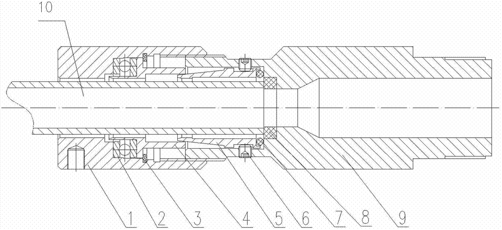
[0013] Such as figure 1 A specific embodiment shown includes a movable sleeve 1 and a fixed sleeve 9, and the movable sleeve 1 and the fixed sleeve 9 are screwed together.

[0014] The movable sleeve 1 is provided with a locking sleeve 4 that is rotatably connected with the movable sleeve 1, and the locking sleeve 4 is provided with a limit boss that protrudes outward. The sleeve hole of the movable sleeve 1 is a stepped hole, and one end of the large aperture is used In connection with the fixed sleeve 9, one end of the large aperture of the locking sleeve 4 is provided with a thrust bearing 2, and the thrust bearing 2 is clamped on the limit boss on the locking sleeve 4 and the inner step surface of the movable sleeve 1, and the locking sleeve The limit boss on 4 is provided with a retaining ring 3 on the side away from the thrust bearing 2, and the retaining ring 3 is fixed on the movable sleeve 1. So that the locking sleeve 4 can rotate in the movable sleeve 1 but cannot ...


PUM


Abstract

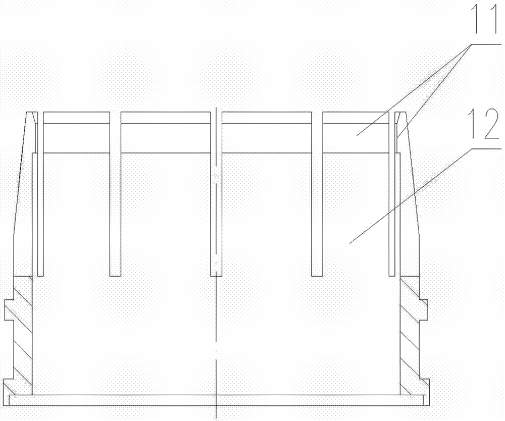
The invention discloses an oxygen blowing holder, which comprises a movable sleeve and a fixed sleeve, wherein the movable sleeve is in threaded connection with the fixed sleeve; a locking sleeve rotationally connected with the movable sleeve is arranged in the movable sleeve; a connecting sleeve is arranged in the fixed sleeve; a connecting sleeve limiting step surface for limiting the axial displacement of the connecting sleeve and an oxygen blowing tube limiting step surface for limiting the axial displacement of an oxygen blowing tube are arranged in the fixed sleeve; an elastic element is arranged between one end of the connecting sleeve far from the movable sleeve and the connecting sleeve limiting step surface in the fixed sleeve; the fixed sleeve is provided with a set bolt for locking the connecting sleeve; and one end of the connecting sleeve close to the movable sleeve is provided with a plurality of elastic clamping sections. A sealing ring is arranged at a connecting position of the oxygen blowing holder and the oxygen blowing tube; during connection, the compression of the oxygen blowing tube facing the sealing ring is easy to realize; and the position has good sealing performance, and hardly leaks air and returns fire. Moreover, the operation of connecting the oxygen blowing holder and the oxygen blowing tube is simple and convenient, and the connecting speed ishigh.

Description

technical field [0001] The invention relates to a pipe connector, in particular to an oxygen blowing holder used for connecting an oxygen suction pipe and an oxygen gas source. Background technique [0002] At present, the smelting process needs to use an oxygen pipe to manually blow oxygen to the tap hole. Most of the connection methods use the oxygen blowing pipe to be directly inserted into the rubber pipe and fastened with iron wire. Occurs backfire burns the operator. Contents of the invention [0003] The technical problem to be solved by the present invention is to provide an oxygen blowing holder for connecting the oxygen blowing pipe and the gas source, so that the connection between the oxygen blowing pipe and the oxygen blowing pipe has good sealing performance and is not easy to leak and temper. [0004] In order to solve the above-mentioned technical problems, the present invention includes a movable sleeve and a fixed sleeve, the movable sleeve and the fixed...

Claims


Application Information

Patent Timeline
Patent Type & Authority Patents(China)
IPC IPC(8): F16L19/03
Inventor 顾子成刘生健
Owner 济南盛达冶金科技有限公司
Learn More