RFRD (radio frequency identification)-based timing method, device and system
A radio frequency identification and chip identification technology, which is applied in the field of communication, can solve the problem of being unable to accurately calculate the time when the timing chip is activated.
- Summary
- Abstract
- Description
- Claims
- Application Information
AI Technical Summary
Problems solved by technology
Method used
Image
Examples
Embodiment 1
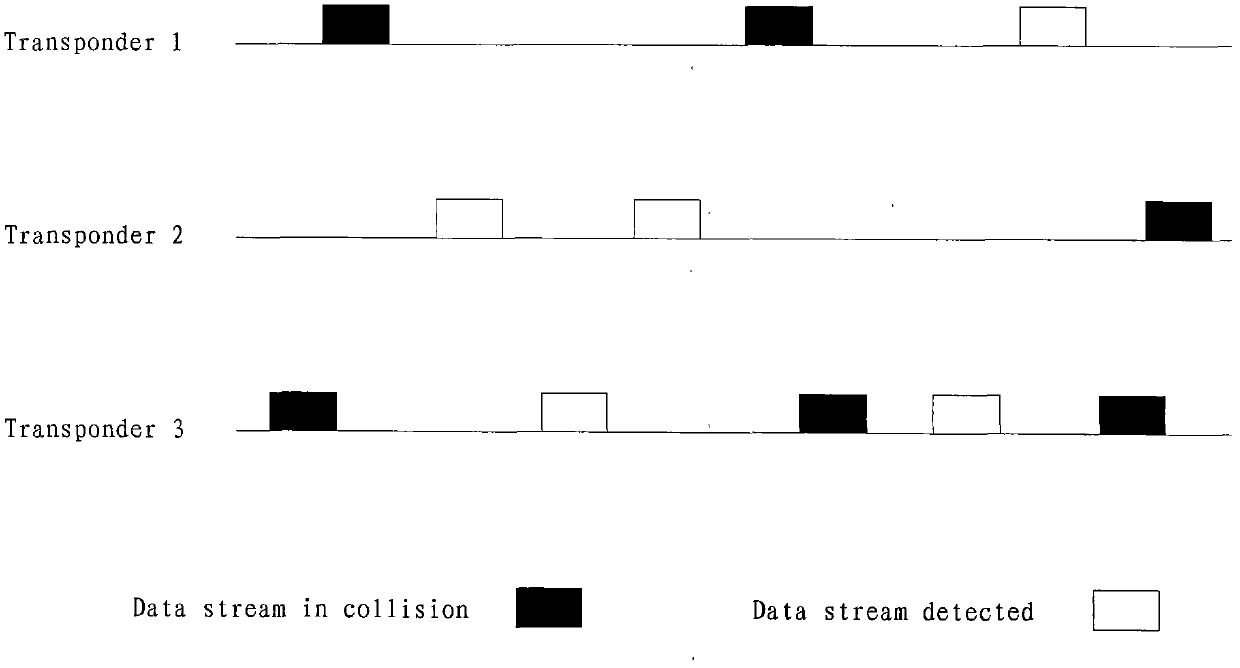
[0025] The embodiment of the present invention proposes a timing method based on device identification, including:
[0026] 101. When the timing chip is activated, calculate the time difference between the time when the timing chip sends out the chip identification number and the time when the timing chip is activated;
[0027] Specifically, the activation of the timing chip may be: in the passive working mode, the charging of the timing chip is completed; in the semi-active working mode, the timing chip is woken up.
[0028] 102. In the preset maximum number of time slots N max and the minimum number of slots N min Randomly choose an integer N between random ;
[0029] 103. Elapsed time N random × the duration of each time slot t s Afterwards, send a timing data packet to the reader, the timing data packet includes at least the chip identification number of the timing chip and the time difference between the time when the timing chip sends out the chip identification num...
Embodiment 2
[0032] An embodiment of the present invention provides a timing method based on radio frequency identification, including:
[0033] 201. Preset the maximum number of time slots N max , the minimum number of slots N min and the duration t of each time slot s ;
[0034] 202. After the timing chip is activated, calculate the time difference between the time when the timing chip sends out the chip identification number and the time when the timing chip is activated;
[0035] Specifically, the activation of the timing chip may be: in the passive working mode, the charging of the timing chip is completed; in the semi-active working mode, the timing chip is woken up.
[0036] 203. In the maximum number of time slots N max and the minimum number of slots N min Randomly choose an integer N between random ;
[0037]204. Every time interval N random ×t s , sending a timing data packet to the reader, wherein the timing data packet includes at least the chip identification number ...
Embodiment 3
[0044] An embodiment of the present invention provides a timing device based on radio frequency identification, such as image 3 shown, including:
[0045] The counter module 301 is used to calculate the time difference between the time when the timing chip sends out the chip identification number and the time when the timing chip is activated when the timing chip is activated;
[0046] Specifically, the activation of the timing chip may be: in the passive working mode, the charging of the timing chip is completed; in the semi-active working mode, the timing chip is woken up.
[0047] Random number generation module 302, for the preset maximum number of time slots N max and the minimum number of slots N min Randomly choose an integer N between random ;
[0048] Sending module 303, for elapsed duration N random × the duration of each time slot t s Afterwards, send a timing data packet to the reader, the timing data packet includes at least the chip identification number o...
PUM
 Abstract
Description
Claims
Application Information
 - R&D
- Intellectual Property
- Life Sciences
- Materials
- Tech Scout
- Unparalleled Data Quality
- Higher Quality Content
- 60% Fewer Hallucinations
Browse by: Latest US Patents, China's latest patents, Technical Efficacy Thesaurus, Application Domain, Technology Topic, Popular Technical Reports.
© 2025 PatSnap. All rights reserved.Legal|Privacy policy|Modern Slavery Act Transparency Statement|Sitemap|About US| Contact US: help@patsnap.com


