Bus handle with bolt

A bus and latch technology, applied to vehicle parts, special positions of vehicles, transportation and packaging, etc., to achieve the effect of standing comfortably

Inactive Publication Date: 2012-01-25
吴利明
View PDF0 Cites 7 Cited by
  • Summary
  • Abstract
  • Description
  • Claims
  • Application Information

AI Technical Summary

Problems solved by technology

But when the bus brakes or makes a sharp turn, since the handle is softly connected to the fixed crossbar of the bus, the handle is free to shake, and it is difficult for people to stabilize their bodies in situ through this handle.

Method used


Image

  • Bus handle with bolt
  • Bus handle with bolt
  • Bus handle with bolt

Examples


Embodiment Construction

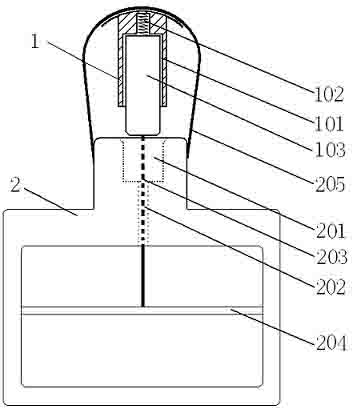
[0014] see figure 1 , the crossbar pin 1 is provided with a bolt 103, one end of the bolt 103 is installed in the bolt groove 101 of the crossbar pin through a spring 102, the other end is connected with the pin belt 203 of the pull handle 2, and the other end of the pin belt 203 passes through the pin belt channel 202 Installed on the pin control rod 204 of the pull handle 2, the pull handle 2 is provided with a pin hole 201 corresponding to the latch 103, and 205 is a connecting belt.

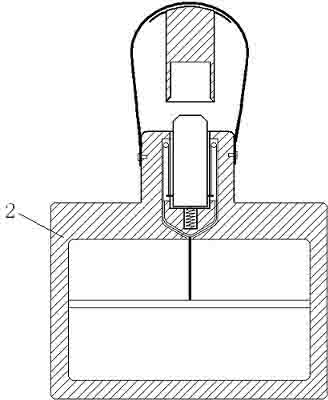
[0015] The crossbar pin 1 of the present invention is installed on the fixed crossbar. When in the suspended state, the pull handle 2 is suspended by the soft connection belt 205 and the pin belt 203, and can shake; ; When the present invention will be rigidly connected to the fixed cross bar, grab the pull handle and pull down the pin control bar 204, then the latch 103 part is pinned into the pin hole 201 of the pull handle 2, and the latch 103 is inserted in the latch groove 101 and the pi...


PUM


Abstract

The invention discloses a bus handle with a bolt, which has the function of the existing bus handle and also can cause a handle rod to be forcedly fixed on the fixed cross rod of the bus when the bus handle is held by a passenger. The bus handle has all functions of the existing bus handle, and the handle rod can be forcedly fixed on the fixed cross rod of the bus as required when the bus handle is held by a passenger, so that the passenger can more stably and comfortably stand on the bus.

Description

technical field [0001] The invention relates to a bus handle, in particular to a bus handle with a latch. Background technique [0002] At present, handles are generally installed on buses, and the handles of the handles are installed on several fixed cross bars on the bus through soft belts, so that standing passengers can hold the handles with their hands to stabilize their bodies, which plays an important role in the stable driving of the bus. big effect. But when the bus brakes or makes a sharp turn, because the handle is softly connected to the fixed cross bar of the car, the handle is free to shake, so it is difficult for people to stabilize their health in situ by this handle. It is often seen that when braking suddenly or making a sharp turn, passengers are dangling like hanging objects while grabbing the handle. If what the passenger grabs at this moment is the fixed pull handle that is hard-connected on the fixed cross bar, just be easy to stabilize health. Due ...

Claims


Application Information

Patent Timeline
Patent Type & Authority Applications(China)
IPC IPC(8): B60N3/02
Inventor 吴利明
Owner 吴利明
Why Eureka
Try Eureka