
Engine cover propping mechanism

A technology of engine hood and front nacelle, applied in the direction of upper structure, upper structure sub-assembly, transportation and packaging, etc.

Inactive Publication Date: 2012-01-25
CHONGQING CHANGAN AUTOMOBILE CO LTD
View PDF5 Cites 6 Cited by
  • Summary
  • Abstract
  • Description
  • Claims
  • Application Information

AI Technical Summary

Problems solved by technology

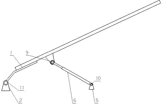
However, due to the limited stroke of the air pressure strut, the distance between the hinge seat 9 of the inner panel of the hood and the rotation axis 11 of the hood hinge is generally small.

Method used


Image

  • Engine cover propping mechanism
  • Engine cover propping mechanism
  • Engine cover propping mechanism

Examples


Embodiment Construction

[0013] Referring to the accompanying drawings, specific embodiments of the present invention will be described in detail.

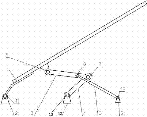
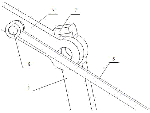
[0014] Such as figure 2 As shown, the generator cover propping mechanism includes connecting rod 3, crank 4, air pressure strut 6, air pressure strut hinged seat 5, crank hinged seat 12, engine hood inner plate hinged seat 9 and the like. The air pressure strut hinged seat 5 and the crank hinged seat 12 are fixed on the front side beam of the engine room, and the engine hood inner plate hinged seat 9 is arranged on the engine hood inner plate. One end of connecting rod 3 is hinged with engine hood inner plate hinge seat 9 to connect the engine hood, and the other end is hinged with an end of crank 4 . The other end of the crank 4 is hinged with the crank hinge seat 12 (10 is the hinge center point). One end of the air pressure strut 6 is hinged on the air pressure strut hinge seat 5, and the other end is hinged with the middle part of the connecting ro...


PUM


Abstract

The invention discloses an engine cover propping mechanism. The engine cover propping mechanism comprises an air pressure stay bar, an air pressure stay bar hinge seat and an engine cover inner plate hinge seat, wherein the air pressure stay bar hinge seat is fixed to an upper side beam of a front engine room; one end of the air pressure stay bar is hinged on the air pressure stay bar hinge seat; and the engine cover inner plate hinge seat is arranged on an engine cover inner plate. The engine cover propping mechanism is characterized by also comprising a connecting rod, a crank and a crank hinge seat, wherein one end of the connecting rod is hinged with the engine cover inner plate hinge seat and is connected with an engine cover; the other end of the connecting rod is hinged with one end of the crank; a limiting structure for limiting the connecting rod is arranged on the crank; the other end of the crank is hinged with the crank hinge seat; the crank hinge seat is fixed to the upper side beam of the front engine room and is positioned between the hinge point of the engine cover and the front engine room and the air pressure stay bar hinge seat; and the other end of the air pressure stay bar is hinged with the middle part of the connecting rod. In the engine cover propping mechanism, a force application action point of the air pressure stay bar is changed by a four-connecting-rod mechanism, so that an open angle of the engine cover is increased without selecting and using air pressure stay rods of different specifications when the stroke of the air pressure stay bar is small.

Description

technical field [0001] The invention relates to an engine cover in an automobile, in particular to an engine cover propping mechanism. Background technique [0002] The engine cover is an important part of automobile products, and it is a necessary channel for users to inspect and repair the power system. Therefore, in terms of ease of use, the switch should be flexible, light and free, and the maximum opening can be limited by stays or air pressure support rods, and the opening should be sufficient to ensure convenient inspection and maintenance. [0003] At present, many engine hoods are supported by air pressure struts. The specific installation structure is as follows: figure 1 Shown is: one end of the air pressure strut 6 is hingedly connected to the air pressure strut hinge seat 5 on the upper side beam of the front engine room (10 is its hinge center point), and the other end is hingedly connected to the hinge seat 9 of the inner panel of the engine hood. When the e...

Claims


Application Information

Patent Timeline
Patent Type & Authority Applications(China)
IPC IPC(8): B62D25/12
Inventor 李斌王远宏张瑞鹏
Owner CHONGQING CHANGAN AUTOMOBILE CO LTD
Learn More