Splicing camera lamps using single lamp to synchronously control multiple lamps

A technology of synchronous control and video lights, which is applied in the field of video lights, can solve the problems of inability to quickly and synchronously control multiple video lights, inconvenience for photographers, etc., and achieve the effect of saving lighting time and good contact

Active Publication Date: 2012-02-15
FUZHOU F&V PHOTOGRAPHIC EQUIP
View PDF10 Cites 2 Cited by
  • Summary
  • Abstract
  • Description
  • Claims
  • Application Information

AI Technical Summary

Problems solved by technology

When using the existing video lights with splicing function, it is still necessary to adjust each video light one by one, and it is impossible to quickly and synchronously control the spliced ​​multiple video lights, which will cause inconvenience to the photographer's work

Method used


Image

  • Splicing camera lamps using single lamp to synchronously control multiple lamps
  • Splicing camera lamps using single lamp to synchronously control multiple lamps
  • Splicing camera lamps using single lamp to synchronously control multiple lamps

Examples


Embodiment Construction

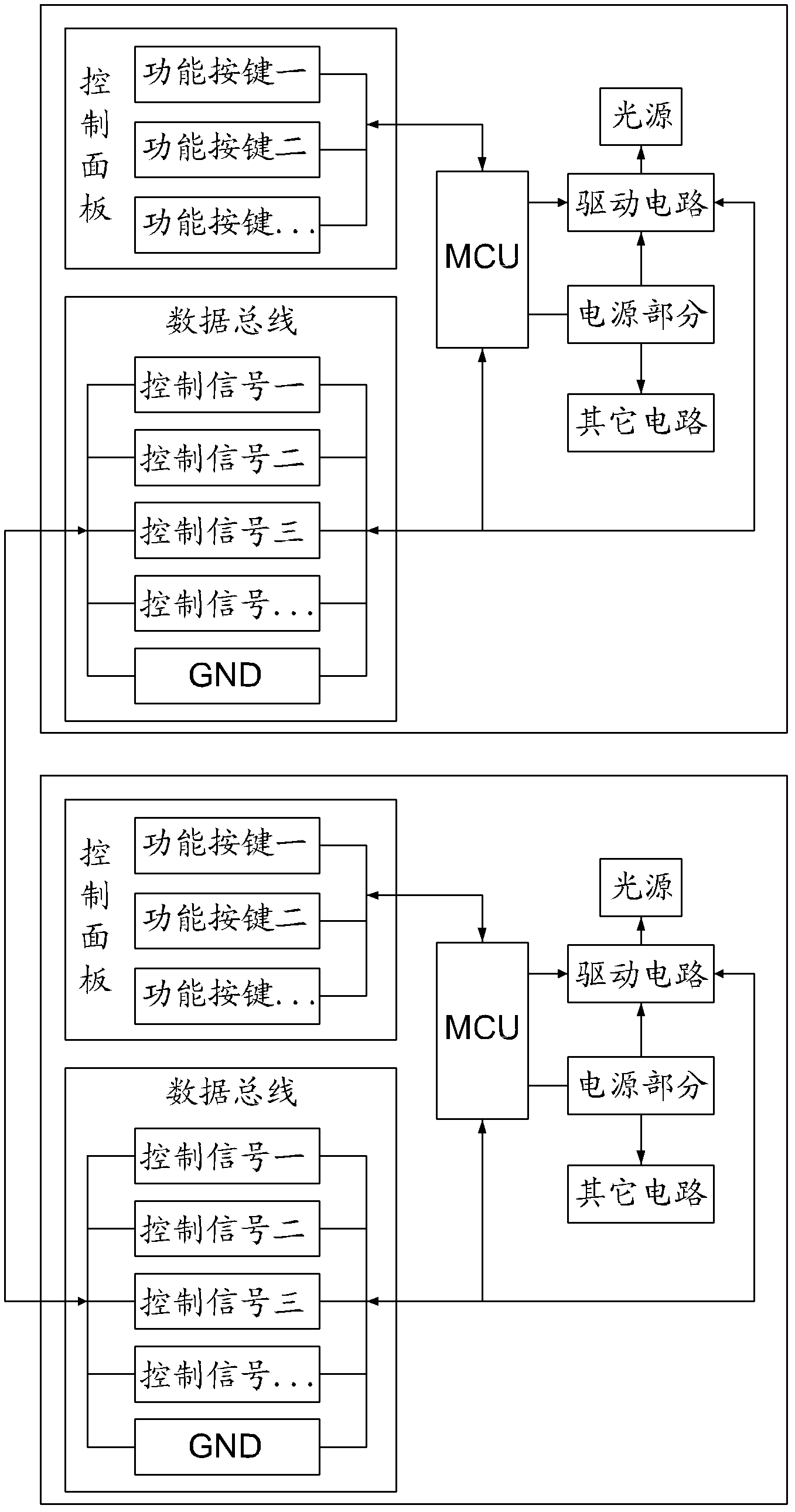
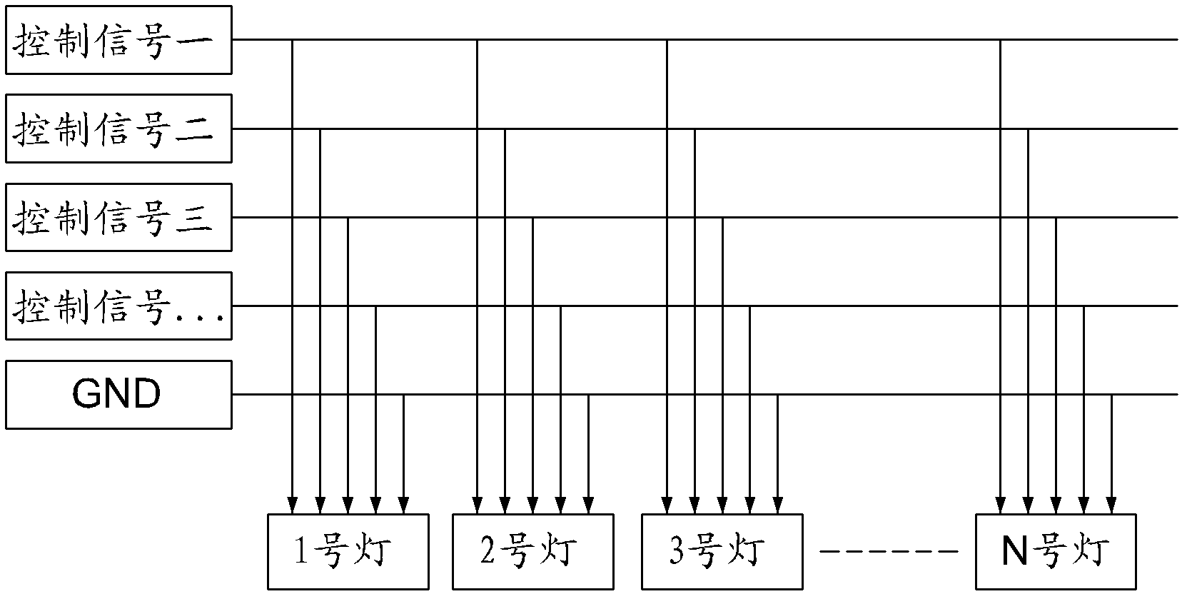
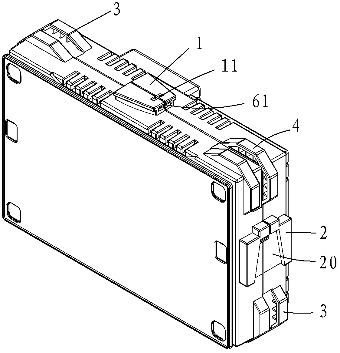
[0023] see Figure 1 to Figure 6 As shown, the embodiments of the present invention will be described in detail.

[0024] like figure 1 , figure 2 , a splicable video light that can synchronously control multiple lights by a single light. Each video light is connected to another video light through a splicing structure. Each video light includes a control panel, an MCU, a circuit to be controlled, a power supply, and a data bus. The control panel is connected to the MCU, the MCU is connected to the circuit to be controlled, the power supply is connected to the MCU and the circuit to be controlled, the MCU and the circuit to be controlled are all connected to the data bus, and the data bus is correspondingly connected to the camera The data bus of another video light connected to the light. In this embodiment, the circuit to be controlled includes a driving circuit and a light source connected in sequence, one end of the driving circuit is respectively connected to the MCU ...


PUM


Abstract

The invention provides splicing camera lamps using a single lamp to synchronously control multiple lamps. Each camera lamp is connected to another camera lamp through a splicing structure, wherein each camera lamp comprises a control panel, an MCU (Micro Control Unit), a to-be-controlled circuit, a power supply and a data bus, wherein the control panel is connected to the MCU; the MCU is connected to the to-be-controlled circuit; the power supply is connected to the MCU and the to-be-controlled circuit; the MCU and the to-be-controlled circuit are both connected to the data bus; the data bus is correspondingly connected to the data bus of another camera lamp which is connected to the camera lamp; the to-be-controlled circuit comprises a driving circuit and a light source which are connected in turn; one end of the driving circuit is respectively connected to the MCU and the data bus; the other end of the driving circuit is connected to the light source; and the power supply is also connected to the driving circuit and the light source. The linkage of the circuit is realized by the camera lamps which are spliced with each other, and a user can synchronously adjust the spliced camera lamps through the control panel of any camera lamp.

Description

【Technical field】 [0001] The invention relates to a light source device for photography and videography, in particular to a splicable videography light. 【Background technique】 [0002] There are very few video lights with splicing function on the market now. The video light with splicing function generally has the advantages of lightness and portability of a single light; and its splicing function can well solve the disadvantage of insufficient brightness of a single light. [0003] The existing video light single light with splicing function generally includes devices such as a light emitting body, a power supply compartment, a circuit, and a control panel mounted on a housing. When each single light is not spliced, it is a video light with independent power supply, independent illuminant and independent circuit control. Because each single light is an independent control circuit, when the spliced ​​video lights are in use, it is still necessary to adjust the brightness, ...

Claims


Application Information

Patent Timeline
Patent Type & Authority Applications(China)
IPC IPC(8): G03B15/05H05B37/02F21V23/06F21V19/00F21V17/16
Inventor 詹小明
Owner FUZHOU F&V PHOTOGRAPHIC EQUIP
Why Eureka
Try Eureka