
Assisted takeoff system of airplane

A technology of aircraft and slides, which is applied to aircraft parts, motor vehicles, special-purpose ships, etc., and can solve problems such as complex structure of catapults, limited range of operations, and heavy weight

Inactive Publication Date: 2012-02-22
刘建平
View PDF4 Cites 10 Cited by
  • Summary
  • Abstract
  • Description
  • Claims
  • Application Information

AI Technical Summary

Problems solved by technology

[0002] Due to the limited length of warships, carrier-based aircraft usually need to use assisted takeoff methods to make the aircraft leave the warship at a speed greater than or equal to the aircraft's ground speed, otherwise the aircraft cannot take off normally.
For example, there are usually two ways to take off when an aircraft carrier-borne aircraft takes off. One is to use a ski jump to take off. This method requires that the weight of the aircraft should not be too large when it takes off, that is, it cannot carry more fuel and ammunition. Therefore, its combat effectiveness The range is greatly limited; the other is to use catapult take-off. Although this method has a small weight limit for the aircraft, the structure of the catapult is complicated and the manufacturing precision is high, so the cost is also high and the difficulty is great. Basically, The monopoly of the United States and a very small number of countries

Method used


Image

  • Assisted takeoff system of airplane
  • Assisted takeoff system of airplane
  • Assisted takeoff system of airplane

Examples


Embodiment Construction

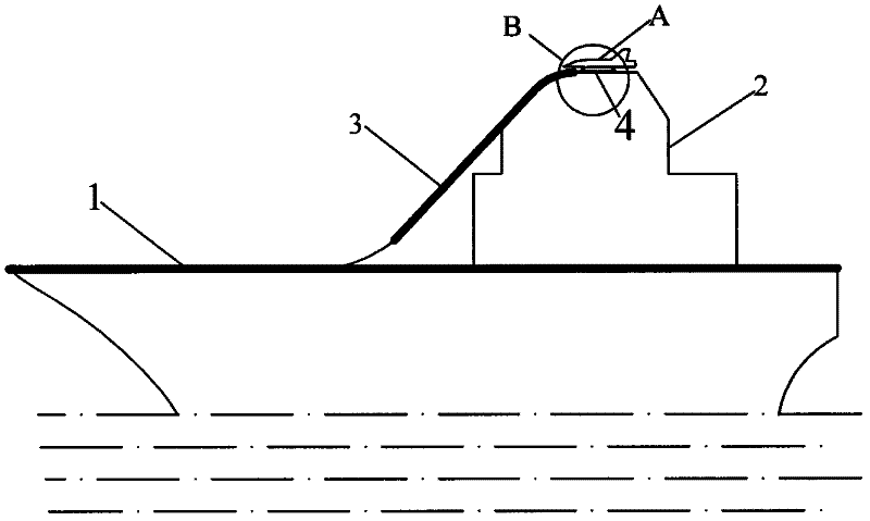
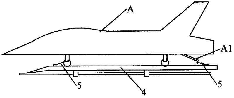
[0016] Such as figure 1 and figure 2 As shown, the present invention provides an embodiment of an aircraft auxiliary take-off system.

[0017] The aircraft auxiliary take-off system includes: a slope slideway 3 that can convert gravitational potential energy into kinetic energy and a tackle 4 that cooperates with the slideway 3 and moves along it. One end of the slideway 3 is smoothly connected with the aircraft carrier flight deck 1, and the other end is connected with the The aircraft carrier island 2 is fixed, and the start end of the slideway located at the island end 2 is in a horizontal state.

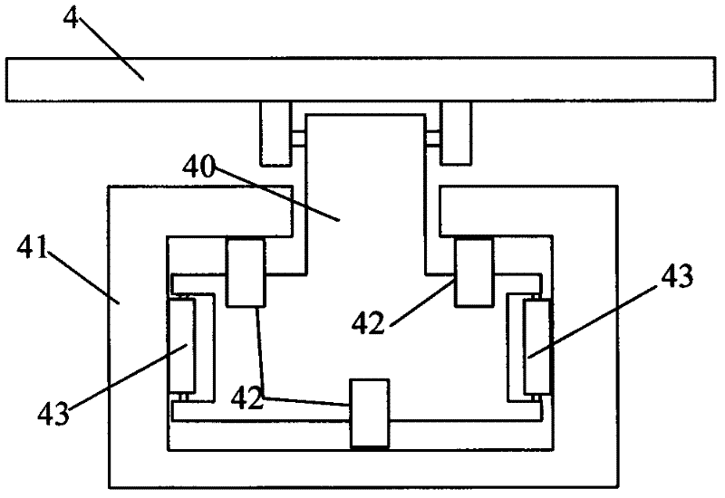
[0018] Specifically, a pulley 4 is provided at the starting end of the slideway 3, and three slide blocks 40 hinged thereto are provided at the bottom of the slideway 4, and the guide groove 41 on the slide block 40 and the slideway 3 Sliding fit, that is, the lower part of the slider 40 is embedded in the guide groove 41 on the slideway 3 , and the upper part of the slider 40...


PUM


Abstract

The invention discloses an assisted takeoff system of an airplane. The assisted takeoff system comprises a slope slideway and pulleys, wherein one end of the slideway is smoothly connected with a horizontal runway, and the other end of the slideway is fixed to an aircraft carrier island; the starting end of the slideway on the aircraft carrier island is in a horizontal state; and each pulley is provided with fixing and unlocking devices which are arranged between the airplane and the pulleys and used for preventing bumping. When the assisted takeoff system is used, the airplane is arranged at the starting end of the slideway arranged at an aircraft carrier island end; then, the pulleys and the airplane dive to accelerate. When the airplane reaches the bottom end of the slope, a position switch controls an electromagnet motor to work to remove the fixation, and the airplane continuously accelerates and rises to the sky. The system utilizes the self gravitational potential energy of the airplane to assist the airplane to take off, so that the difficulties that limits of ski jump type takeoff on airplane weight and a catapult is difficult to manufacture can be overcome, auxiliary thrust augmentation required in airplane takeoff can be reliably, efficiently and stably provided, so that the airplane quickly reaches takeoff initial velocity, and the assisted takeoff system not only can be used for assisting the airplane to take off on the aircraft carrier, but also can be used for assisting the airplane to take off on an island in a short distance.

Description

technical field [0001] The invention relates to the technical field of aircraft assisted take-off, in particular to a short-distance assisted take-off system for aircraft on aircraft carriers and narrow islands. Background technique [0002] Due to the limited length of warships, carrier-based aircraft usually need to use assisted takeoff methods to make the aircraft leave the warship at a speed greater than or equal to the aircraft's ground speed, otherwise the aircraft cannot take off normally. For example, there are usually two ways to take off when an aircraft carrier-borne aircraft takes off. One is to use a ski jump to take off. This method requires that the weight of the aircraft should not be too large when it takes off, that is, it cannot carry more fuel and ammunition. Therefore, its combat effectiveness The range is greatly limited; the other is to use catapult take-off. Although this method has a small weight limit for the aircraft, the structure of the catapult ...

Claims


Application Information

Patent Timeline
IPC IPC(8): B64F1/36
CPCB64F1/04B63G11/00
Inventor 刘建平
Owner 刘建平
Learn More