

Deep sea standpipe segment model bidirectional forcing vibration experimental apparatus under effect of oblique uniform flow
A deep-sea riser and segmented model technology, applied in the field of ocean engineering, can solve problems such as inability to simulate special sea conditions, and achieve the effect of avoiding scale effects
- Summary
- Abstract
- Description
- Claims
- Application Information
AI Technical Summary
Problems solved by technology
Method used
Image


Examples
Embodiment Construction
[0025] In order to make the object, technical solution and advantages of the present invention clearer, the present invention will be further described in detail below in conjunction with the accompanying drawings and embodiments. It should be understood that the specific embodiments described here are only used to explain the present invention, not to limit the present invention.
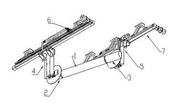
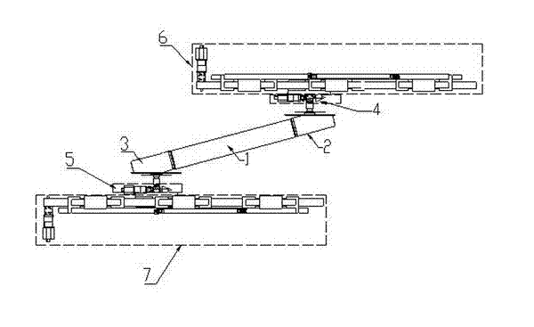
[0026] Such as figure 1 , figure 2 and image 3 As shown, the device includes: a deep-sea riser module 1, a first end prosthesis module 2, a second end prosthesis module 3, a first vertical sliding module 4, a second vertical sliding module 5, and a first horizontal sliding module 6. The second horizontal sliding module 7 and the measurement analysis control module 8, wherein: the two ends of the deep-sea riser module 1 are respectively connected with the first end prosthesis module 2 and the second end prosthesis module 3, and the first vertical sliding module 4 are respectively connected with...
PUM
| Property | Measurement | Unit |
|---|---|---|
| Diameter | aaaaa | aaaaa |
| Length | aaaaa | aaaaa |
Abstract
Description
Claims
Application Information