
Hydraulic rocking roller bracket

A roller and hydraulic technology, applied in the direction of winding strip, thin material handling, transportation and packaging, can solve the problems of deviation and difficult adjustment of the steel strip, and achieve the effect of accurate adjustment, convenient reset and adjustment, and improved work efficiency.

Inactive Publication Date: 2012-03-07
WUXI SHUNTE METAL PROD
View PDF7 Cites 2 Cited by
  • Summary
  • Abstract
  • Description
  • Claims
  • Application Information

AI Technical Summary

Problems solved by technology

[0003] The invention provides a swingable roller bracket, which can well solve the problem that the deviation of the steel belt is difficult to adjust

Method used


Image

  • Hydraulic rocking roller bracket
  • Hydraulic rocking roller bracket
  • Hydraulic rocking roller bracket

Examples


Embodiment Construction

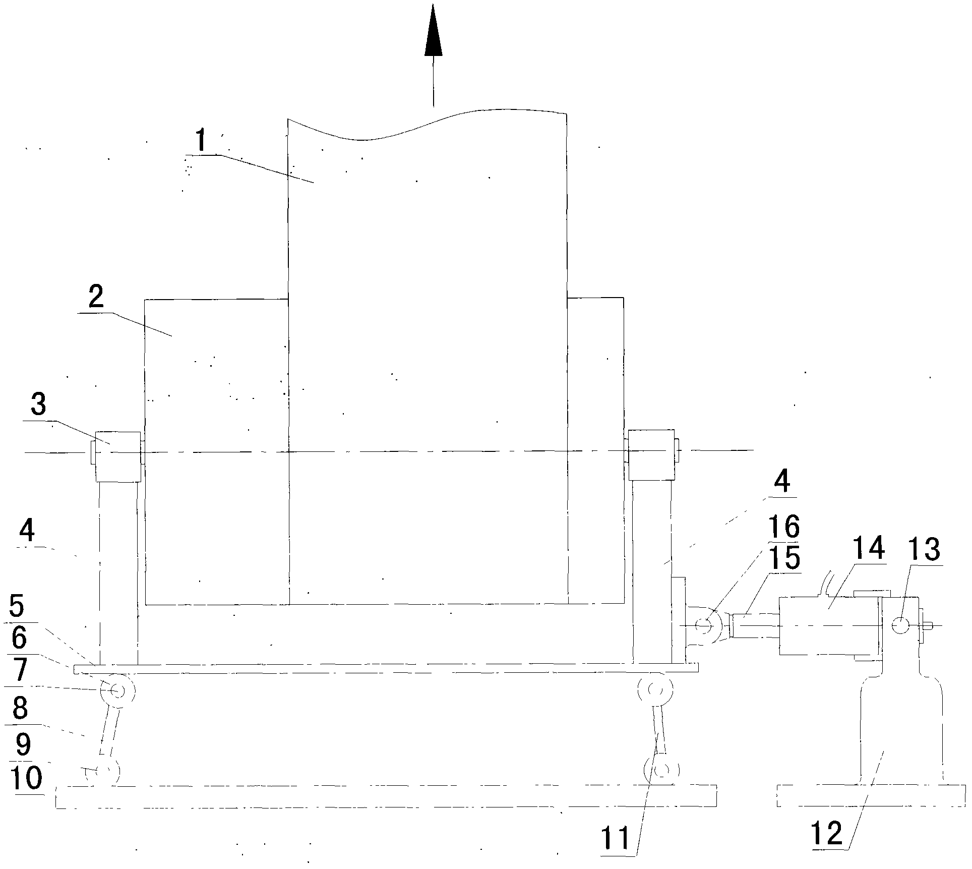
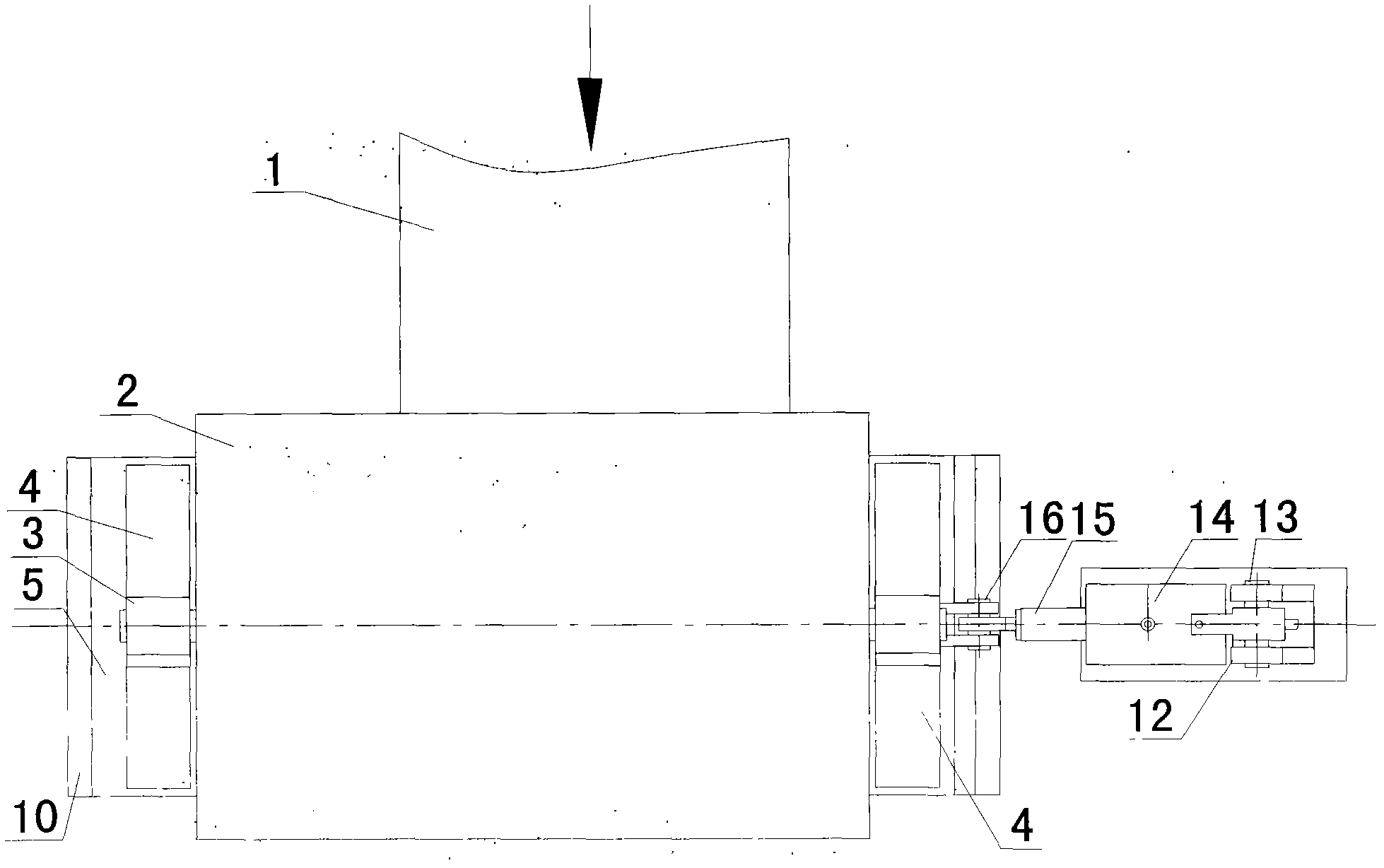
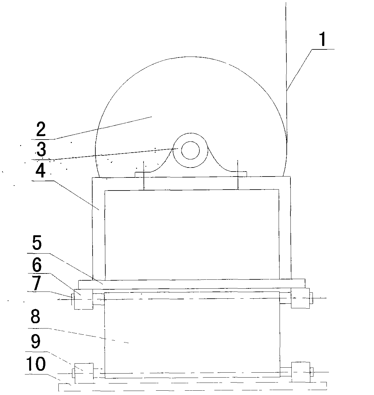
[0015] Such as Figures 1 to 3 As shown, a specific embodiment of the present invention is provided. In the figure, the steel strip 1 moves along the direction of the arrow on the roller 2, and the two shafts of the roller 2 are installed on a pair of first axle sleeves 3 on the bracket 4 , the bracket 4 is fixed on the bottom plate 5, when the steel belt 1 moves under the drive of the motor, the roller 2 rotates on the bracket 4, and there are two rocking plates under the bottom plate 5: the first rocking plate 8 and the second rocking plate 11, two Each rocking plate has a pair of rocking plate rotating shafts 7 up and down, and its two ends are respectively inserted into two pairs of second axle sleeves 6 fixed on the lower end of the base plate and two pairs of third axle sleeves 9 fixed on the base 10; When the rocking plate can stably support the roller 2, the positions of the two rocking plates are set to be not parallel to each other. When one of them is vertical, the ...


PUM


Abstract

The invention relates to a hydraulic rocking roller bracket, which comprises a roller, a first shaft sleeve, a bracket, a base plate, a base and a hydraulic rocking adjusting mechanism, wherein the hydraulic rocking adjusting mechanism comprises a hydraulic cylinder, a first rocking plate and a second rocking plate; the upper ends of the two rocking plates are in rotating connection with the base plate while the lower ends are in rotating connection with the base; a tail end of the hydraulic cylinder is in rotating connection with the upper end of a hydraulic cylinder bracket fixed on the base; a front end of a hydraulic rod is in rotating connection with the bracket at one end of the roller; a pair of rocking plate rotating shafts is respectively arranged on the upper and lower parts of the two rocking plates; two ends of the rocking plate rotating shafts at the upper end of the two rocking plates are respectively inserted into two pairs of second shaft sleeves fixed at the bottom of the base plate; two ends of the rocking plate rotating shafts at the lower end of the two rocking plates are respectively inserted into two pairs of third shaft sleeves fixed on the base; the positions of the two rocking plates are unparallel to each other; and when one rocking plate is vertical, the other rocking plate is inclined inwards. In the hydraulic rocking roller bracket, the hydraulic rod drives the roller bracket to adjust along a horizontal direction, thereby being accurate in adjustment, higher in efficiency and saving manpower and material resources.

Description

technical field [0001] The invention relates to a hydraulic swing roller support. Background technique [0002] In steel strip galvanizing, coiling, cold rolling and other processes, positioning or supporting rollers are used when feeding or receiving materials. The rollers are usually installed on the bracket through the rotating shaft, but the usual brackets are fixed on the base, so The rollers can only rotate on the bracket and cannot move laterally, and the steel belt will inevitably deviate during the transportation process. It is necessary to manually adjust the steel belt with the help of tools, which is laborious and laborious, which increases labor consumption and makes it difficult to improve work efficiency. Contents of the invention [0003] The invention provides a swingable roller bracket, which can well solve the problem that the deviation of the steel belt is difficult to adjust. [0004] In order to achieve the above purpose, the following technical solu...

Claims


Application Information

Patent Timeline
Patent Type & Authority Applications(China)
IPC IPC(8): B65H23/038
Inventor 王一新黎立
Owner WUXI SHUNTE METAL PROD
Learn More