Side pressing block adjusting mechanism, stamping die and stamping equipment

A technology of adjusting mechanism and adjusting parts, which is applied in the field of stamping processing, can solve the problems of inconvenient assembly and disassembly, difficulty in meeting production needs, etc., and achieve the effect of simple structure

Inactive Publication Date: 2021-05-28
CWB AUTOMOTIVE ELECTRONICS
View PDF0 Cites 0 Cited by
  • Summary
  • Abstract
  • Description
  • Claims
  • Application Information

AI Technical Summary

Problems solved by technology

[0005] The purpose of the present invention is to solve the problem that the conventional stamping dies in the prior art adopt a large block structure and the adjustment structure is arranged inside the die base, which is inconvenient to assemble and disassemble, and it is difficult to meet the requirements of bending products with a thickness less than 0.4mm and long strips. Due to the problem of production demand, a side pressure block adjustment mechanism is proposed, and a modular stamping die and stamping equipment with the side pressure block adjustment mechanism

Method used


Image

  • Side pressing block adjusting mechanism, stamping die and stamping equipment
  • Side pressing block adjusting mechanism, stamping die and stamping equipment
  • Side pressing block adjusting mechanism, stamping die and stamping equipment

Examples


Embodiment 1

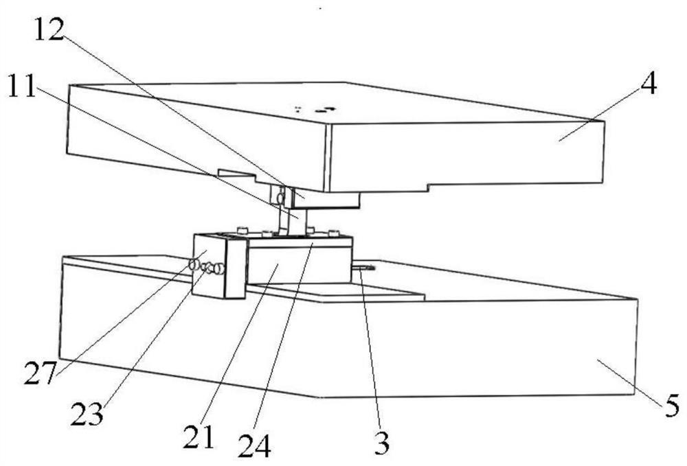
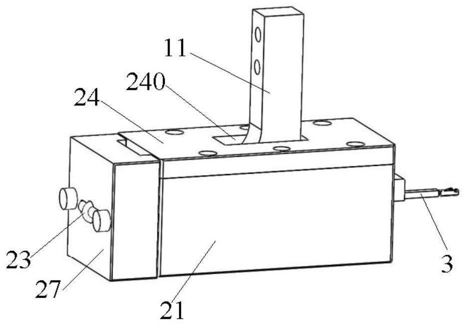
[0053] Such as Figure 1 to Figure 7 The shown side pressure block adjustment mechanism includes an adjustment assembly 1 , a slide assembly 2 , an adjustment mandrel 3 and a blocking member 27 . Wherein, the adjustment assembly 1 includes an adjustment member 11 composed of a body part 111 , an adjustment part 112 and a connection part 113 , a driving part and an adjustment fixing seat 12 . The two opposite sides of the adjustment part 112 are respectively formed with a first action part 114 and a second action part 115 . The sliding assembly 2 includes a base 21 , a sliding block 22 slidably connected to the base 21 , and a reset biasing member 23 for driving the sliding block 22 to reset. The sliding block 22 is provided with a avoidance portion 220 for the adjusting member 11 to enter and exit, and the sliding block 22 can be driven by the adjusting member 11 to slide along a second direction intersecting with the first direction in which the adjusting member 11 enters an...

Embodiment 2

[0065] A kind of stamping die of the present embodiment, such as Figure 1 to Figure 7As shown, the side pressure block adjustment mechanism, the upper mold base 4 and the lower mold base 5 of the first embodiment are included. The adjustment assembly 1 is fixedly installed on the upper mold base 4, specifically, the adjustment fixing base 12 is fixedly installed on the bottom of the upper mold base 4 through fasteners such as bolts, and the connecting part 113 of the adjustment member 11 is fixedly installed on the adjustment part 11 through fastening belts such as bolts. On the fixed seat 12. The lower die base 5 is arranged below the upper die base 4 , opposite to the upper die base 4 , and the sliding assembly 2 is fixedly mounted on the lower die base 5 . It should be noted that the stamping die of this embodiment also includes other conventional structures such as a punch, a die, an upper die assembly such as an upper template, an upper template fixing plate, a stripper...

Embodiment 3

[0068] A stamping device of this embodiment, such as Figure 1 to Figure 7 As shown, the stamping die in Example 2 is included. Other structures, such as the mounting frame, are not described and limited in detail, and are conventional structures of existing stamping equipment.


PUM


Abstract

The invention relates to a side pressing block adjusting mechanism, a stamping die and stamping equipment. The side pressing block adjusting mechanism comprises an adjusting assembly, a sliding assembly and an adjusting core rod, wherein the adjusting assembly comprises an adjusting piece and a driving piece, the adjusting piece is provided with a body part and an adjusting part, an included angle is formed between the body part and the adjusting part, and the adjusting part is provided with a first acting part and a second acting part; the sliding assembly comprises a base, a sliding block and a reset bias piece, an avoiding part for the adjusting piece to enter and exit is arranged on the sliding block, and a first acting piece and a second acting piece are arranged at the two ends of the avoiding part respectively; the adjusting core rod is arranged on the sliding block and used for being connected with a to-be-stamped piece; the body part enters the avoiding part, and the first acting part acts on the first acting piece to drive the sliding block to slide towards one side of the to-be-stamped piece and enable the second acting piece to be located on a retreating path of the second acting part; and the body part retreats from the avoiding part, the first acting part relieves the action with the first acting piece, the second acting part acts on the second acting piece, and the sliding block resets under the action of the reset bias piece. The structure is simple, and the lateral adjusting effect can be achieved.

Description

technical field [0001] The invention relates to the technical field of stamping processing, in particular to a side pressure block adjustment mechanism, a stamping die and stamping equipment. Background technique [0002] With the development of modern industry, stamping processing has developed rapidly and has become an indispensable part of modern processing. Stamping processing uses the power of conventional or special stamping equipment to directly separate the sheet metal in the stamping die. Or directly subjected to deformation force for forming processing, so as to obtain the production technology of products with certain shape, size and performance. [0003] In today's society, electronic products or automotive electronic connector products tend to be miniaturized, high-precision, and high-quality. At the same time, customers have higher and higher quality requirements for products, which brings us metal mold designers. Greater challenges, resulting in a very large-...

Claims


Application Information

Patent Timeline
Patent Type & Authority Applications(China)
IPC IPC(8): B21D37/10B21D43/00
CPCB21D37/10B21D43/003
Inventor 周清泉于国涛李兵周月宇赵建招代亚坤吴栋材王海富
Owner CWB AUTOMOTIVE ELECTRONICS
Why Eureka
Try Eureka