
Turnover pneumatic claw

A technology of pneumatic grippers and grippers, applied in the direction of manipulators, program-controlled manipulators, chucks, etc., can solve problems such as poor turning performance, and achieve reliable control, good turning performance, and good motion performance

Inactive Publication Date: 2012-03-21
董旭
View PDF6 Cites 12 Cited by
  • Summary
  • Abstract
  • Description
  • Claims
  • Application Information

AI Technical Summary

Problems solved by technology

However, at present, this kind of machinery or manipulator has poor turnover

Method used


Image

  • Turnover pneumatic claw
  • Turnover pneumatic claw

Examples


Embodiment Construction

[0011] The present invention will be further described below in conjunction with the accompanying drawings and embodiments.

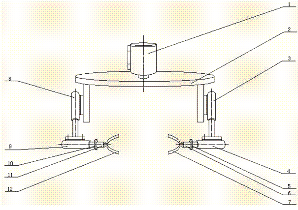
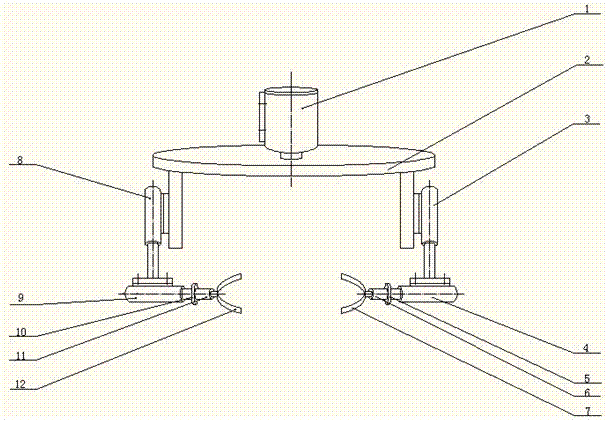
[0012] Such as figure 1 As shown, a reversible pneumatic gripper includes: motor Ⅰ1, rotating plate 2, cylinder Ⅰ3, cylinder Ⅱ4, fixed baffle Ⅰ5, motor Ⅱ6, gripper Ⅰ7, cylinder Ⅲ8, cylinder Ⅳ9, fixed baffle Ⅱ10, Motor Ⅲ11, gripper Ⅱ12. The motor 1 is connected to the rotating plate 2; the cylinder I3 and cylinder III8 are fixed on the rotating plate 2; the cylinder I3 is connected to the cylinder II4, and the cylinder III8 is connected to the cylinder IV9; Claw Ⅱ12 is installed with interference fit; the rod of cylinder Ⅱ4 is connected with fixed baffle Ⅰ5 by welding, the rod of cylinder Ⅳ9 is connected with fixed baffle Ⅱ10 by welding; motor Ⅱ6 is connected with fixed baffle Ⅰ5, and motor Ⅲ11 is connected with fixed baffle Ⅱ10 connect.

[0013] The gripper moves up and down through the cylinder Ⅰ3 and cylinder Ⅲ8; the gripper is opened and closed th...


PUM


Abstract

The invention discloses a turnover pneumatic claw, which comprises a motor I, a rotating plate, a cylinder I, a cylinder II, a fixed baffle I, a motor II, a claw I, a cylinder III, a cylinder IV, a fixed baffle II, a motor III and a claw II, wherein a shaft of the motor I is connected with the rotating plate through a key; the motor II and the claw I are installed in the manner of interference fit; the motor III and the claw II are installed in the manner of interference fit; a rod of the cylinder II is connected with the fixed baffle I in a welding manner; the rod of the cylinder IV is connected with the fixed baffle II in a welding manner; the other linkage is threaded connection; the rod of the cylinder I and the rod of the cylinder III are used for driving the claw to move up and down; the rod of the cylinder II and the rod of the cylinder IV can move left and right, and thus the claw can open and close; the claw rotates horizontally under the action of the rotation of the motor I; and the claw turns over under the action of the synchronous rotation of the motor II and the motor III. The turnover pneumatic claw has the advantages of reliable control, excellent moving performance, excellent turnover property, wide developing prospect, and the like.

Description

[0001] technical field [0002] The invention relates to a reversible pneumatic gripper. Background technique [0003] In the machining and injection molding industries, many stations are for picking up and flipping objects. This kind of operation is generally simple in action and highly repeatable. At present, many picking machines or manipulators have been designed for this demand, including electric, hydraulic, and pneumatic, etc. But the turnover of this kind of machinery or manipulator is relatively poor at present. Contents of the invention [0004] The object of the present invention is to provide a reversible pneumatic gripper in order to solve the above problems. [0005] In order to achieve the above object, the present invention adopts following technical scheme: [0006] A reversible pneumatic gripper, including motor Ⅰ, rotating plate, cylinder Ⅰ, cylinder Ⅱ, fixed baffle Ⅰ, motor Ⅱ, gripper Ⅰ, cylinder Ⅲ, cylinder Ⅳ, fixed baffle Ⅱ, motor Ⅲ, gripper Ⅱ; ...

Claims


Application Information

Patent Timeline
Patent Type & Authority Applications(China)
IPC IPC(8): B25J9/04B25J15/08
Inventor 董旭姜晓利仲富惟姜胜磊田玉胜秦梅
Owner 董旭
Learn More