Variable flow-rate ejector and fuel cell system having the same

a technology of flow-rate ejector and fuel cell system, which is applied in the direction of machine/engine, cell component details, cell components, etc., can solve the problems of increased cost, complex structure and control of fuel cell system, and inability to accurately control the actuator

Inactive Publication Date: 2005-02-22
HONDA MOTOR CO LTD
View PDF12 Cites 57 Cited by
  • Summary
  • Abstract
  • Description
  • Claims
  • Application Information

AI Technical Summary

Benefits of technology

In consideration of the above circumstances, an object of the present invention is to provide a variable flow-rate ejector for precisely controlling the flow rate based on pressure control, by using a simple structure without employing electrical control.
According to the above structure, the first fluid supplied to the nozzle is ejected from through the opening at the heat of the nozzle. In the nozzle, the needle which is movable along the central axis is inserted. Therefore, the area of the opening around the needle in the opening at the head of the nozzle can be changed by adjusting the position of the needle, for example, by making the needle protrude from the opening. Accordingly, the flow rate of the first fluid, which is ejected from the gap between the nozzle and the needle, can be controlled.
Here, the first diaphragm separates the inside of the nozzle and the third-fluid chamber, and the position of the first diaphragm is determined based on the balance between the pressure of the first fluid (supplied to the nozzle) and the pressure of the third fluid (supplied to the third-fluid chamber). The second diaphragm separates the third-fluid chamber and the fourth-fluid chamber, and the position of the second diaphragm is determined based on the balance between the pressure of the third fluid (supplied to the third-fluid chamber) and the pressure of the fourth fluid (supplied to the fourth-fluid chamber). Accordingly, the flow rate of the mixture of the first fluid and the second fluid, which is output from the diffuser, can be reliably controlled only by performing a mechanical control based on the pressure balance of the first, third, and fourth fluids. Therefore, in comparison with precise control of the flow rate using an electric driving device or the like, reliable flow-rate control can be performed based on the pressure while using a simpler structure.
According to the fuel cell system, when the fuel discharged from the fuel cell at a specific flow rate is merged with fuel which is newly supplied to the fuel cell so as to recirculate the fuel, the flow rate of the mixture of the discharged fuel and the newly-supplied fuel can be reliably controlled only by performing a mechanical control based on the pressure balance of the first, third, and fourth fluids. Accordingly, in comparison with precise control of the flow rate using an electric driving device or the like, reliable flow-rate control can be performed based on the pressure while using a simpler structure. Therefore, it is possible to prevent the control of the fuel cell system from being complicated, and to reduce the cost necessary for constructing the system.
According to this structure, the differential pressure between the pressure of the oxidizing gas supplied to the fuel cell and the pressure of the fuel supplied from the fuel supply section is applied to the first diaphragm. Conversely, the differential pressure between the pressure of the third fluid and the pressure of the fourth fluid is applied to the second diaphragm, wherein this differential pressure corresponds to the differential pressure between the electrodes of the fuel cell. Accordingly, if the amount of fuel consumed in the fuel cell is changed (e.g., decreased) and thus the differential pressure between the electrodes of the fuel cell is changed (in the above example, increased), then the first and second diaphragms are displaced according to the changes in the differential pressures which are respectively applied to the diaphragms. Therefore, the position of the needle in the nozzle is changed, so that the flow rate of the mixture of the discharged fuel and the newly-supplied fuel can be suitably controlled. Accordingly, in comparison with precise control of the flow rate using an electric driving device or the like, reliable flow-rate control can be performed based on the pressure while a simpler structure is used and a required differential pressure between the electrodes, which is necessary for the fuel cell, is maintained.

Problems solved by technology

Therefore, the structure and the control of the fuel cell system are complicated.
Therefore, the costs may be increased so as to improve the precision of the actuator, or the size of the actuator may be increased.

Method used


Image

  • Variable flow-rate ejector and fuel cell system having the same
  • Variable flow-rate ejector and fuel cell system having the same
  • Variable flow-rate ejector and fuel cell system having the same

Examples


Embodiment Construction

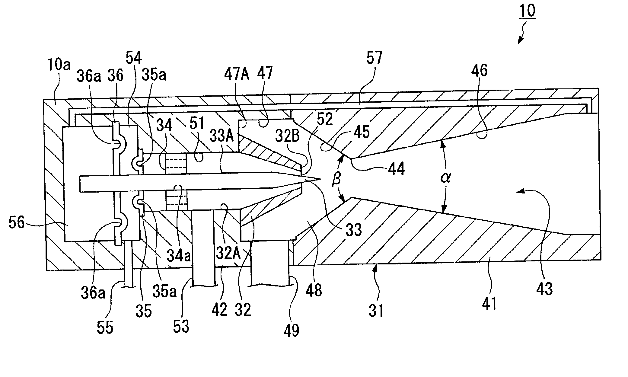
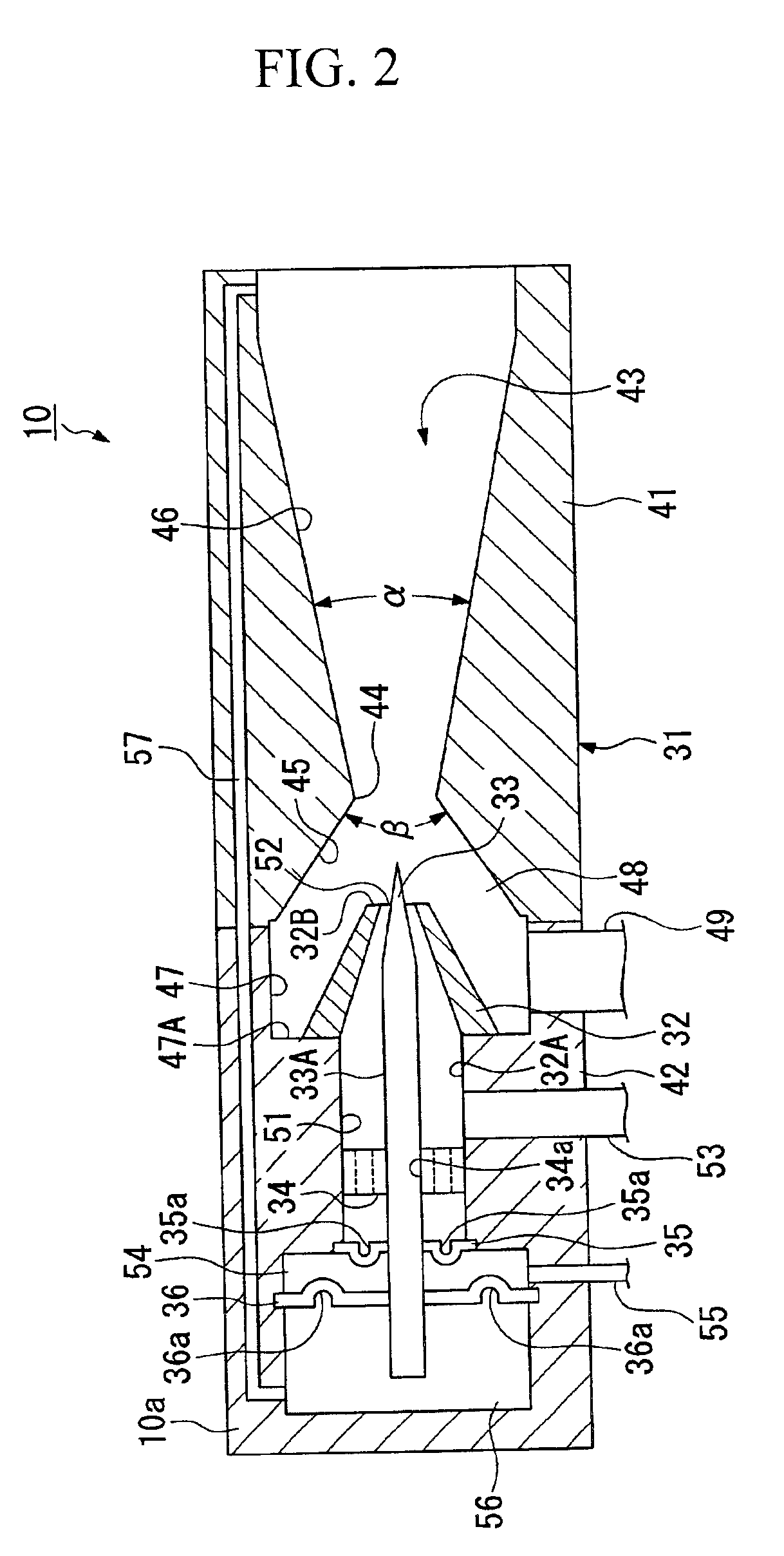
Hereinafter, the structure of the variable flow-rate ejector as an embodiment of the present invention will be explained with reference to the drawings.

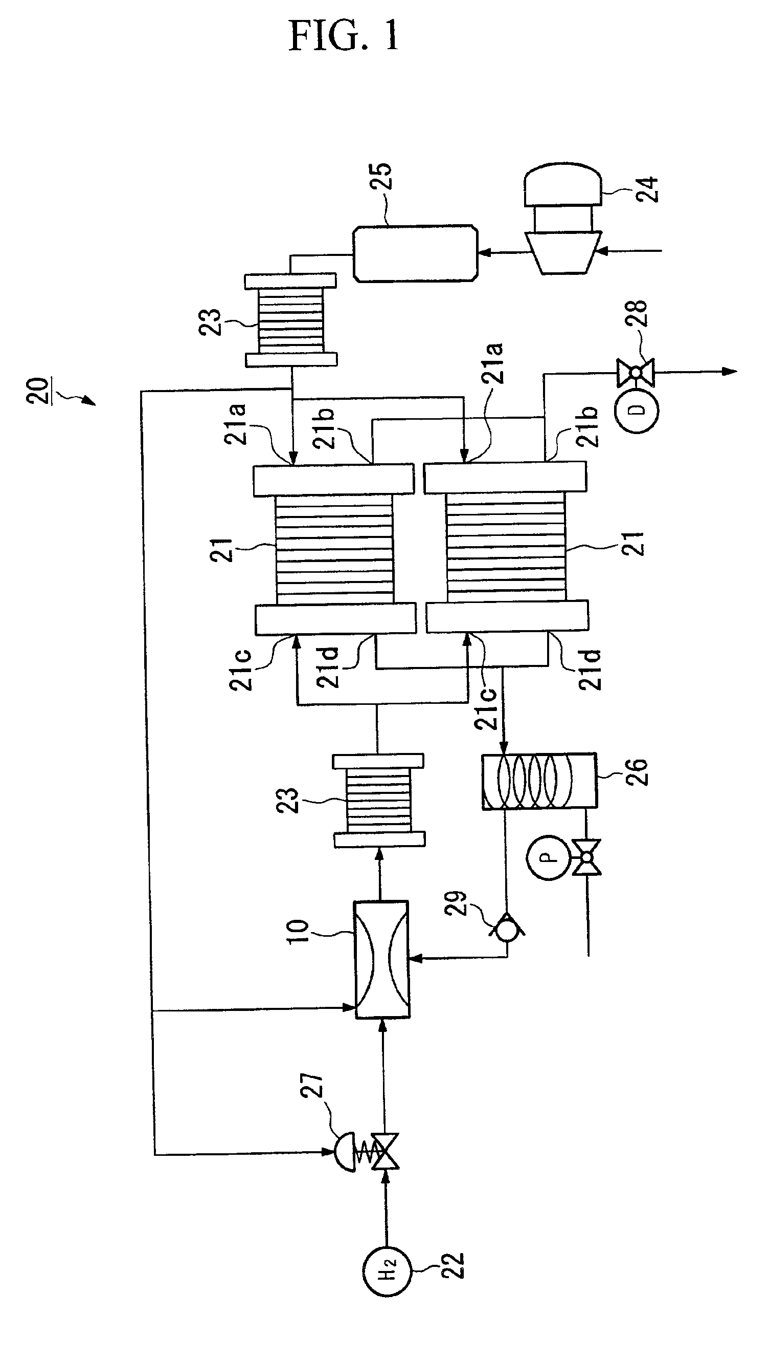
FIG. 1 is a diagram showing the structure of a fuel cell system 20 which has a variable flow-rate ejector 10 as an embodiment of the present invention. FIG. 2 is a cross-sectional side view of the variable flow-rate ejector 10.

The variable flow-rate ejector 10 is provided in the fuel cell system 20 which is built, for example, in an electric vehicle or the like. The fuel cell system 20 includes the variable flow-rate ejector 10, a fuel cell 21, a fuel supply section 22, a humidifying section 23, an oxidizing gas supply section 24, a heat exchanging section 25, a water separating section 26, and a fuel supply side pressure control section 27.

In the fuel cell 21, each unit cell has an anode and a cathode which are provided on either side of a solid polymer electrolyte membrane which may be a solid polymer ionic exchange membrane. A plu...


PUM

PropertyMeasurementUnit
pressureaaaaaaaaaa
pressureaaaaaaaaaa
pressureaaaaaaaaaa

Abstract

A variable flow-rate ejector for precisely controlling the flow rate based on pressure is disclosed. The ejector has a simple mechanical structure which comprises a nozzle for ejecting a first fluid; a diffuser into which a second fluid is drawn due to a negative pressure produced around the first fluid, where the first and second fluids are merged; a third-fluid chamber formed by first and second diaphragms attached to the needle, and the body of the ejector; and a fourth-fluid chamber formed by the second diaphragm and the body. The area of an opening around the needle in the opening at the head of the nozzle is changed by displacement of the needle along the central axis according to movement of first and second diaphragms which move in accordance with the pressure produced by the first fluid, the third fluid, and the fourth fluid.

Description

BACKGROUND OF THE INVENTION1. Field of the InventionThe present invention relates to an ejector, connected to a fuel cell or the like, for merging fuel discharged from the fuel cell with fuel which is newly supplied, so as to recirculate the fuel. In particular, the present invention relates to a technique for varying the flow rate of the fuel.2. Description of the Related ArtIn conventional solid polymer membrane-type fuel cells, each cell has an anode and a cathode which are provided on either side of a solid polymer electrolyte membrane. A plurality of such cells are stacked so as to form a stack, which is called the “fuel cell” in the following explanations. In the fuel cell, hydrogen, which functions as fuel, is supplied to the anode, while air, which functions as an oxidizing gas, is supplied to the cathode. The catalytic reaction on the anode generates hydrogen ions, and the hydrogen ions are transferred to the cathode via an electrolyte membrane. The transferred hydrogen ion...

Claims


Application Information

Patent Timeline
Patent Type & Authority Patents(United States)
IPC IPC(8): F04F5/48F04F5/46F04F5/00F04F5/18H01M8/02H01M8/04H01M8/10
CPCF04F5/461F04F5/48H01M8/02H01M8/04097H01M8/04104Y02E60/50H01M8/04126H01M8/04156H01M2008/1095
Inventor SUGAWARA, TATSUYAKIZAKI, SHIGEKAZUNUIYA, YOSHIO
Owner HONDA MOTOR CO LTD
Why Eureka
Try Eureka