Slide rail structure and automatic business device

The technology of an automatic transaction device and a slide rail is applied to a device for accepting coins, a casing of an automatic teller machine, parts of an automatic teller machine, etc. Cost-reducing, easy-to-operate effects

Inactive Publication Date: 2012-03-28
OKI ELECTRIC IND CO LTD
View PDF4 Cites 1 Cited by
  • Summary
  • Abstract
  • Description
  • Claims
  • Application Information

AI Technical Summary

Problems solved by technology

[0006] in the above Figure 10 In the conventional slide rail structure shown, when installing the slide rail 54, since it is necessary to put the hands or the body inside the device main body 2 and hold the slide rail 54 in a restrained posture, it is difficult to operate and sometimes Make slide rail 54 drop, damage
[0007] In addition, in Figure 11 In the case of the slide rails 64 and 74 shown, if there are two slide rails 64 as a set, the same slide rails cannot be used on the left and right in terms of the structure of the hook 61, so it is necessary to prepare two slide rails for the left and right. Types of slide rails, there is a problem of increasing costs
In the case of the slide rail 74, since the rivet 71, which is another part different from the slide rail 74, needs to be prepared and installed, there is a problem of increasing cost as with the slide rail 64

Method used


Image

  • Slide rail structure and automatic business device
  • Slide rail structure and automatic business device
  • Slide rail structure and automatic business device

Examples


Embodiment 1

[0025] (constitute)

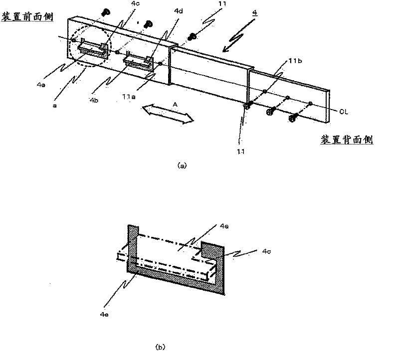
[0026] figure 1 (a) is the overall configuration diagram of the slide rail 4 of embodiment 1, figure 1 (b) for figure 1 (a) Enlarged view of part a of the dotted line part. As shown in this figure, the slide rail 4 of Embodiment 1 is equipped with: L-shaped curved portions 4a, 4b on the side surface of the device front side of the slide rail 4, and the L-shaped curved portions 4a, 4b are as follows: figure 1 (b) The U-shaped punching part 4e of the hatched part shown in (b) is punched out and formed by L-shaped bending; 4, and is configured such that a threaded hole 11b for fixing the unit 3 and the slide rail 4 is provided on one side surface of the slide rail 4 on the back side of the device main body 2. Notches 4c, 4d are provided on the device back side of the L-shaped bent portions 4a, 4b.

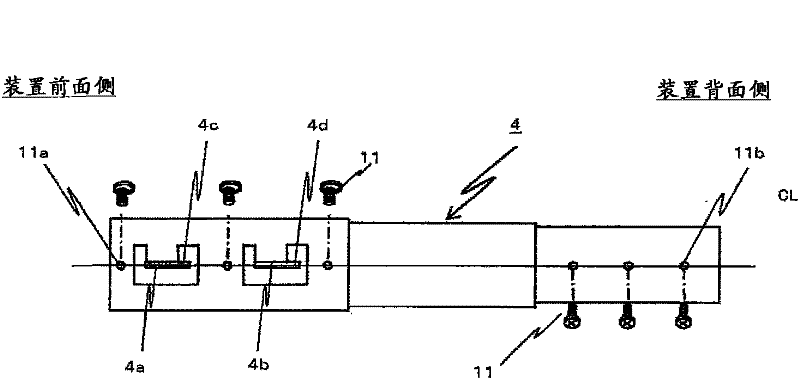
[0027] figure 2 is a side view of the slide rail 4. As shown in the figure, the L-shaped bent portions 4 a, 4 b and the threaded holes 11 a, 11 b are...

Embodiment 2

[0046] (constitute)

[0047] Figure 6 (a) is the configuration diagram of the slide rail 14 of embodiment 2, Figure 6 (b) for Figure 6 (a) Enlarged view of part a of the dotted line part. As shown in this figure, the slide rail 14 of Embodiment 2 has L-shaped curved portions 14a, 14b opposite to the L-shaped curved portions 4a, 4b of the slide rail 4 of Embodiment 1 in the direction of arrow A, so as to achieve easier installation. Purpose on device body 2.

[0048] That is, the slide rail 14 of the second embodiment is provided with: L-shaped curved portions 14a, 14b which are formed by connecting one side surface of the slide rail 14 on the side of the device main body 2 such as Figure 6 (b) The U-shaped punching part 14e of the oblique line part is punched and formed by L-shaped bending; and the threaded hole 11a is used to fix the device main body 2 and the slide rail 14 by screws 11, Furthermore, the slide rail 14 is configured such that a screw hole 11 b for fix...


PUM


Abstract

A slide rail structure configured to mount a unit in a chassis, includes a first side slide rail including a first chassis-engaging slide member having a first side L-shaped projection portion projecting outward of a side of the first chassis-engaging slide member, and a first unit-engaging slide member slidably coupled to the first chassis-engaging slide member and configured to hold to one side of the unit. A second side slide rail includes a second chassis-engaging slide member having a second side L-shaped projection portion projecting outward of a side of the second chassis-engaging slide member, and a second unit-engaging slide member slidably coupled to the second chassis-engaging slide member and configured to hold to another side of the unit. The chassis has a first fitting hole in one side thereof, the first fitting hole being configured to receive the first side L-shaped projection portion so as to fix the first chassis-engaging slide member to said side of the chassis, and has a second fitting hole in an opposite side of the chassis, the second fitting hole being configured to receive the second side L-shaped projection portion so as to fix the second chassis-engaging slide member to the opposite side of the chassis.

Description

technical field [0001] The present invention relates to a slide rail structure capable of supporting and drawing out a unit in a device main body by a slide rail, and an automatic transaction device having the slide rail structure. Background technique [0002] Generally, in automatic transaction machines such as automatic teller machines installed in financial institutions and automatic ticket vending machines installed in stations and airports, slide rails are used for maintenance of mounted units and installation of media. Pull the unit out from the back side of the device body. [0003] For example, if Figure 10 As shown, two slide rails 54 are arranged left and right in a group, and they are fixed on the device body 2 and unit 3 with screws 11, and the unit 3 can be drawn out from the device body 2 in the direction of arrow A, or can be moved to the device body. 2. Storage unit 3 (for example, refer to Patent Document 1). In addition, in this figure, the upper right ...

Claims


Application Information

Patent Timeline
Patent Type & Authority Applications(China)
IPC IPC(8): G07D11/00G07F17/42
CPCG07F19/205A47B88/044A47B88/43
Inventor 久松猛
Owner OKI ELECTRIC IND CO LTD
Why Eureka
Try Eureka