Postweld heat treatment method of welded joint of pipelines with different specifications

A post-weld heat treatment and welded joint technology, applied in heat treatment furnaces, heat treatment equipment, furnaces, etc., can solve problems such as adverse effects on the performance and life of joints, inability to obtain, and unreasonable temperature distribution.

Active Publication Date: 2012-04-11
SUZHOU NUCLEAR POWER RES INST +2
View PDF10 Cites 28 Cited by
  • Summary
  • Abstract
  • Description
  • Claims
  • Application Information

AI Technical Summary

Problems solved by technology

The temperature distribution characteristics and maximum temperature of post-weld heat treatment have an important impact on the performance of the joint: if the temperature distribution is unreasonable, there will still be a large residual stress in the joint after heat treatment, which will have an adverse effect on the performance and life of the joint; if

Method used


Image

  • Postweld heat treatment method of welded joint of pipelines with different specifications
  • Postweld heat treatment method of welded joint of pipelines with different specifications
  • Postweld heat treatment method of welded joint of pipelines with different specifications

Examples


Embodiment 1

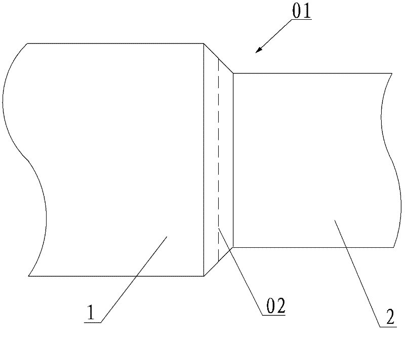
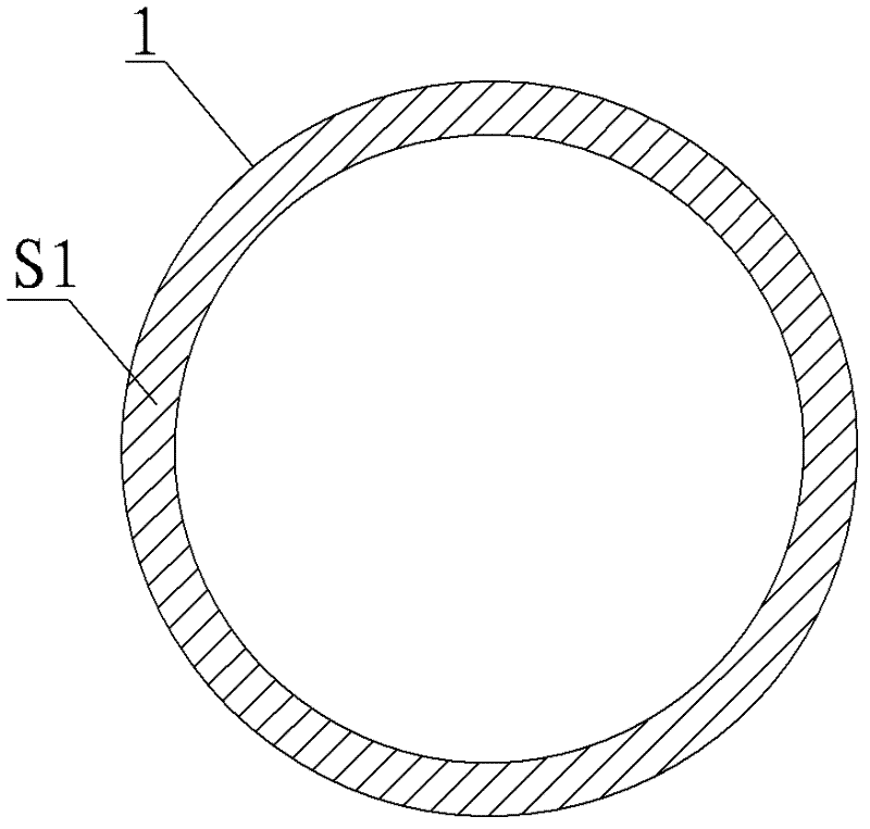
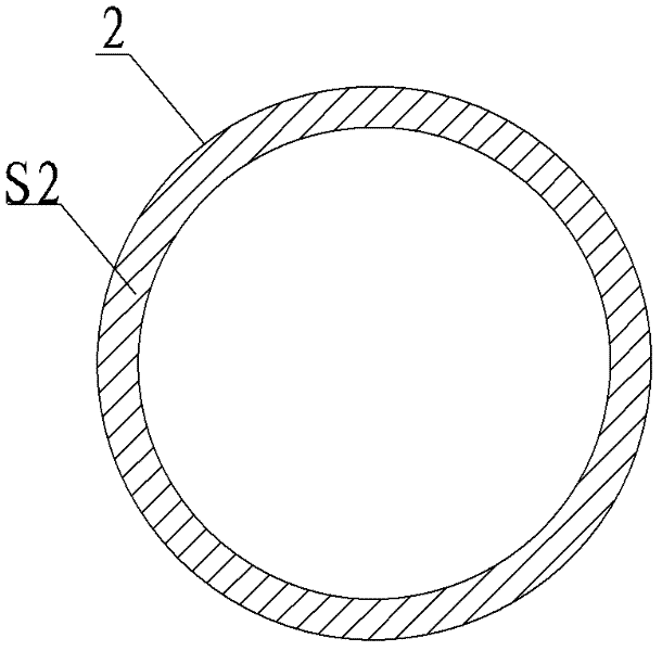
[0048] A pressure pipe has a welded joint composed of P22+P91 steel. The specification of P91 steel is OD556×41(mm), and the specification of P22 steel is OD527×26.5(mm). The welding process requires post-weld heat treatment for the welded joint. The heating width of the post-weld heat treatment is based on the center of the weld width, and each side is 3 times the wall thickness of the P91 steel pipe.

[0049] The post-weld heat treatment method, the specific implementation steps are as follows:

[0050] (1) According to the requirements of the post-weld heat treatment process, the minimum power required for heating is calculated to be 22kW. Considering the power reserve, select a heating element with a power of 30kW, and specifically select a flexible heating rope with a length of 30m, a diameter of 10mm, and a power of 30kW as the heating element;

[0051] (2) Arrangement of thermocouples: select one thermocouple on the welding seam as the temperature control thermocouple...

Embodiment 2

[0057] There is a welded joint made of 12Cr1MoVG+20G steel on a certain pressure pipeline. The specification of 12Cr1MoVG steel is OD506×16(mm), and the specification of 20G steel is OD527×26.5(mm). The welding process requires post-weld heat treatment for the welded joint, and the heating width of the post-weld heat treatment is 100 mm on each side starting from the center of the weld width. The specific implementation steps of the post-weld heat treatment method are as follows:

[0058] (1) Arrangement of thermocouples: 2 thermocouples are arranged in the center of the weld, which are used as temperature control thermocouples for 2 heating plates.

[0059] (2) According to the requirements of the post-weld heat treatment process, the minimum power required for heating is 13.5kW. Considering the power reserve, select 20kW heating elements, specifically, select two block heating elements with an average power of 10kW, an average width of 100mm, and a length of 1600mm and 170...


PUM


Abstract

The invention discloses a postweld heat treatment method of the welded joint of pipelines with different specifications. The welded joint of the pipelines with different specifications comprises two pipelines with different materials and unequal cross sectional areas or equal cross sectional area and a weld joint connecting the two pipelines. In the heat treatment process, heating power compensation is performed on one end which has higher heat transfer capacity to the welded joint, to ensure that the highest temperature point of the heating zone is at the welded joint. In the method, the corresponding heating condition is set according to the different heat transfer conditions of the pipelines at the both ends of the weld joint, the condition that the highest temperature point of the heating zone deviates from the welded joint is effectively avoided, the adverse effects of the traditional postweld heat treatment technology on the properties of the welded joint are overcome and the requirements of the postweld heat treatment technology are met.

Description

technical field [0001] The invention relates to a post-weld heat treatment method for welded joints of pipelines with different specifications, which is suitable for the post-weld heat treatment of welded joints of the same steel or dissimilar steel in industrial pipelines or public pipelines. Background technique [0002] Post-weld heat treatment (PWHT) is a kind of heat treatment to eliminate the residual stress of welded joints and improve the structure and performance of welded joints. The general process is: install thermocouple → arrange heating device → wrap insulation cotton → set heat treatment parameters → heat treatment → post-weld inspection. [0003] There is a type of pipe welding joint in engineering, which is welded by two pipes with different specifications or different materials and specifications. Traditionally, equal-power heating devices are arranged at both ends of the weld to heat-treat such pipe welded joints. Due to the difference in heat transfer c...

Claims


Application Information

Patent Timeline
IPC IPC(8): C21D9/50
Inventor 陈忠兵孙志强
Owner SUZHOU NUCLEAR POWER RES INST
Why Eureka
Try Eureka