Hydraulic loss testing platform and testing method of canned motor rotor system

A technology for shielding motors and hydraulic loss, applied in the mechanical field, can solve the problems of total power loss of motors, limited quantitative relations, inconvenience, etc., and achieve the effect of solving shielding loss

Active Publication Date: 2012-04-11
SHANGHAI JIAO TONG UNIV
View PDF7 Cites 26 Cited by
  • Summary
  • Abstract
  • Description
  • Claims
  • Application Information

AI Technical Summary

Problems solved by technology

The current measurement method is basically to obtain the total power loss of the motor, which is inconvenient for further analysis

Method used


Image

  • Hydraulic loss testing platform and testing method of canned motor rotor system
  • Hydraulic loss testing platform and testing method of canned motor rotor system
  • Hydraulic loss testing platform and testing method of canned motor rotor system

Examples


Example Embodiment

[0042] Example 1

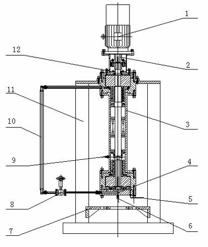
[0043] Such as figure 1 As shown, this embodiment provides a hydraulic loss test platform for a shielded motor rotor system, which includes a variable frequency motor 1, a coupling 2, a shielded motor 3, a static pressure tube 4, a Pitot flowmeter 5, a first pressure sensor 6, The motor tray 7, the electromagnetic flowmeter 8, the second pressure sensor 9, the circulating pipeline 10, the support frame 11 and the sealing ring 12; the variable frequency motor 1 and the shielding motor 3 are connected by a coupling 2, and the shielding motor 3 is connected to A sealing ring 12 is arranged between the couplings 2, a second pressure sensor 9 is arranged in the middle of the shielding motor 3, a static pressure tube 4 and a first pressure sensor 6 are arranged under the shielding motor 3, the shielding motor 3 It is supported by a support frame 11 on which a motor tray 7 is provided. The pitot flowmeter 5 and the electromagnetic flowmeter 8 are located under the shi...

Example Embodiment

[0050] Example 2

[0051] This embodiment provides a method for testing the hydraulic loss of a shielded motor rotor system. The shielded motor involved in this embodiment has a flywheel and auxiliary impeller structure. During the rotation process, the hydraulic loss of the shielded motor is divided into the rotor pressure flow power loss and the rotor shear flow power loss. However, these two kinds of power loss are often mixed with other losses such as water-lubricated bearing power loss and motor shielding loss, and manifested in the form of the total power loss of the shielded motor. The proportion of pressure flow power loss and shear flow power loss in the total loss can only be obtained by calculation, and test data is lacking.

[0052] The test method of this embodiment includes the following steps:

[0053] In the first step, the variable frequency motor 1 is started. The variable frequency motor 1 drives the shield motor 3 through the coupling 2, and the rotor system of ...

Example Embodiment

[0058] Example 3

[0059] This embodiment provides a method for power separation of the shielded motor 3 of Embodiment 2:

[0060] (1) Collect the working parameters of the variable frequency motor 1. The power of the shielded motor 3 is calculated by the voltage, current, power factor of the variable frequency motor 1 and the efficiency of the variable frequency motor 1.

[0061]

[0062] among them: Simplify the total power loss of shielded motor 3 for input, Represents the input voltage of the variable frequency motor, Indicates the current input to the variable frequency motor, Represents the power factor of the variable frequency motor, Indicates the efficiency of the variable frequency motor.
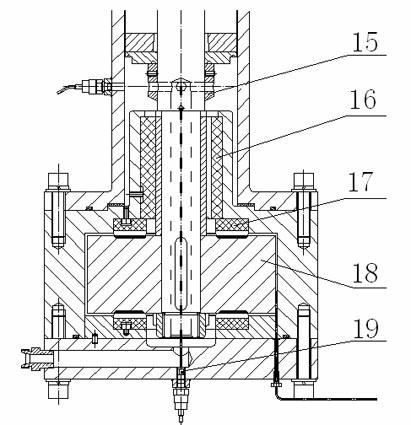
[0063] (2) Collect the indication difference of pressure sensor 6, 9 , To obtain the local high pressure generated by the auxiliary impeller 15;

[0064] Is the indication of the first pressure sensor 6 and the second pressure sensor 9 with Poor, namely:

[0065] ;

[0066] (3) Coll...


PUM


Abstract

The invention discloses a hydraulic loss testing platform and testing method of a canned motor rotor system. The platform comprises a variable frequency motor, a coupling, a canned motor, a static tube, a flow meter, a pressure sensor, a motor pallet, a circulation pipeline, a supporting bracket and a seal ring. According to the invention, a canned motor is dragged and simplified by an external variable frequency motor, thereby eliminating the canning loss of the canned motor; the pressure difference generated by an auxiliary impeller is obtained by the pressure sensor, and the flow through the middle part of the auxiliary impeller is obtained by the flow meter, thereby separating quickly the power loss of the pressure flow of the canned motor; a replaceable auxiliary impeller is mounted at the middle part of the canned motor pump rotor, so at to regulate the amount of the pressure flow; and the clearance between the rotor and the stator of the canned motor pump is changed by replacing a sleeve of the stator, and the impact of different clearances on the power loss of the pressure flow and the shear flow of the canned pump can be studied. By using the hydraulic loss testing platform and testing method provided by the invention, the hydraulic loss of the canned motor can be obtained, which provides reference for the structural parameter optimization of the canned motor.

Description

technical field [0001] The invention belongs to the technical field of machinery, and in particular relates to a hydraulic loss test platform and a test method of a shielded motor rotor system. [0002] Background technique [0003] The function of the nuclear main pump is to drive the high-temperature and high-pressure water in the nuclear island to circulate in the primary circuit, transfer the heat energy of the nuclear fission of the reactor core to the steam generator to generate steam, and drive the steam turbine to generate electricity. Since the water in the primary circuit is radioactive, it is required that the nuclear main pump has no leakage. [0004] There are two main options for nuclear main pumps: shaft-sealed pumps and canned pumps. Although the efficiency of the shaft-sealed pump is higher than that of the shielded pump, it has the defect that dynamic sealing is more difficult in high-temperature and high-pressure environments. In view of the difficulty ...

Claims


Application Information

Patent Timeline
IPC IPC(8): F04D15/00
Inventor 姚振强薛亚波成德龚春鸣徐正松沈洪李梦启李藏雪吕向平
Owner SHANGHAI JIAO TONG UNIV
Why Eureka
Try Eureka