Rotating testing device for vortex-induced vibration of movable inclined riser at lower top of shear flow

A test device and vortex-induced vibration technology, which is applied in the field of marine engineering, can solve the problems of difficult vortex-induced vibration test, small test section distance, and less test data, so as to facilitate upgrading and modification, prolong test time, and increase accuracy Effect

Inactive Publication Date: 2012-04-11
SHANGHAI JIAO TONG UNIV +1
View PDF9 Cites 6 Cited by
  • Summary
  • Abstract
  • Description
  • Claims
  • Application Information

AI Technical Summary

Problems solved by technology

After analysis, the shortcomings of this test technology are: 1. Generally, it can only simulate the vortex-induced vibration of small-scale pipe fittings, and it is difficult to effectively carry out the vortex-induced vibration test under the real Reynolds number
2. Due to the limitation of the length of the deep water tank of the towed marine engineering, the distance of the test section obtained is relatively small, and the measured test data is less
3. Generally, only the vortex-induced vibration of the standpipe in the uniform flow field can be simulated, and the vortex-induced vibration of the standpipe in the stepped flow field cannot be simulated
4. Forced oscillation test cannot be performed
5. The motion of the ocean platform cannot be simulated to study the influence of the motion of the ocean platform on the vortex-induced vibration of the riser

Method used


Image

  • Rotating testing device for vortex-induced vibration of movable inclined riser at lower top of shear flow
  • Rotating testing device for vortex-induced vibration of movable inclined riser at lower top of shear flow
  • Rotating testing device for vortex-induced vibration of movable inclined riser at lower top of shear flow

Examples


Embodiment Construction

[0041] The present invention will be described in detail below through examples. Each example is implemented on the premise of the technical solution of the present invention. Detailed implementation modes and specific operation procedures are given. However, the protection scope of the present invention is not limited to the following Examples.

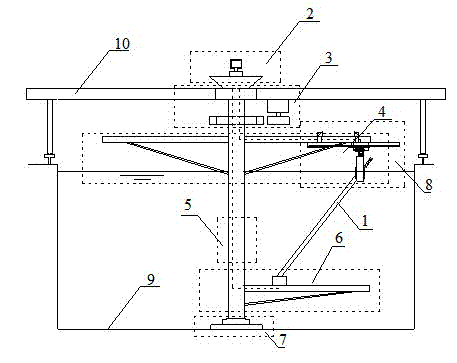
[0042] In an embodiment of the present invention, the vortex-induced vibration rotation test device for an inclined riser with a movable top under shear flow includes a riser model mechanism 1, a measurement analysis system platform module 2, a drive module 3, and a top cantilever module 4 , The cylindrical shaft segmentation module 5, the bottom riser fixing module 6, the bottom support module 7, and the oscillation module 8, wherein the riser model mechanism 1 is fixedly arranged on the oscillation module 8 and the bottom riser fixing module 6, the oscillation module 8 is fixed on the top cantilever module 4, and the cylindrical shaft...


PUM


Abstract

The invention provides a rotating testing device for the vortex-induced vibration of a movable inclined riser at the lower top of a shear flow. The device comprises a riser model mechanism, a measurement and analysis system platform module, a driving module, a top cantilever module, a cylindrical shaft segmentation module, a bottom riser fixing module, a bottom supporting module and an oscillating module, wherein the riser model mechanism is fixedly arranged between the oscillating module and the bottom riser fixing module, the oscillating module is fixedly arranged on the top cantilever module, the cylindrical shaft segmentation module is connected with the bottom supporting module, the driving module, the top cantilever module and the bottom riser fixing module, the bottom supporting module is fixedly arranged on a lifting seat, the driving module is connected with the cylindrical shaft segmentation module and outputs power, the two ends of the top cantilever module are connected with the driving module or the cylindrical shaft segmentation module, and the measurement and analysis system platform module is connected with a riser model, the top cantilever module, the oscillating module and the bottom riser fixing module. The rotating testing device for the vortex-induced vibration of the movable inclined riser at the lower top of the shear flow can simulate a riser with actual size, a shear flow field and top platform movement.

Description

Technical field [0001] The invention relates to a device in the technical field of ocean engineering, in particular to a vortex-induced vibration rotation test device for an inclined riser with a movable top under shear flow. Background technique [0002] According to fluid mechanics, when a columnar structure is placed in the incoming flow at a certain speed, alternating vortices will occur on both sides of it. Associated with the generation and release of vortices, the cylinder will be subjected to lateral and flow pulsating pressure. If the column is elastically supported at this time, the pulsating fluid force will cause the column to vibrate, which in turn will change its wake structure. This problem of fluid structure interaction is called vortex-induced vibration. For example, under the action of ocean currents or ocean platform movement, vortex-induced vibrations will occur on flexible pipes such as offshore platform risers, streamers, submarine pipelines, spar platform...

Claims


Application Information

Patent Timeline
Patent Type & Authority Applications(China)
IPC IPC(8): G01M7/06
Inventor 付世晓陈蓥胡克王俊高
Owner SHANGHAI JIAO TONG UNIV
Why Eureka
Try Eureka