Energy-saving alternating-current contactor with fault clearing lock
An AC contactor, contactor technology, applied in relays, electromagnetic relays, electromagnetic relay details and other directions
- Summary
- Abstract
- Description
- Claims
- Application Information
AI Technical Summary
Problems solved by technology
Method used
Image
Examples
Embodiment 1
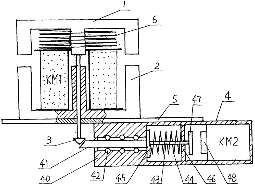
[0037] Such as figure 1 As shown, the chevron-shaped static iron core 2 with the contactor coil KM1 facing upward is fixed on the support plate 5. The support spring 6 makes the moving iron core 1 above the static iron core 2, and the three-phase moving contact Q 1 , Q 2 , Q 3 The rod body of the lock hook 3 is fixed at the center of the lower part of the movable iron core 1, and the rod body passes through the center hole of the static iron core 2 and the through hole on the supporting plate 5 to support An anti-failure lock 4 is installed under the plate 5, and the head of the tongue rod 41 of the anti-failure lock 4 is close to the center line of the iron hook 3.
[0038] The structure of the mechanical part of the lock 4 is as follows: the lock tongue 41 and the ball 42 are installed in the slot core hole in the front of the lock body 40, and the connecting rod 43 in the middle cavity of the lock body 40 is sleeved with a return spring 44, and the front end of the connecting r...
Embodiment 2
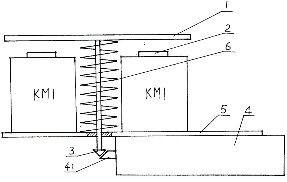
[0041] This embodiment is basically the same as Example 1, except that the electrical part of the fault lock 4 is structured as Figure 5 As shown, it is exactly the same as the second technical solution described above, and will not be repeated here.
Embodiment 3
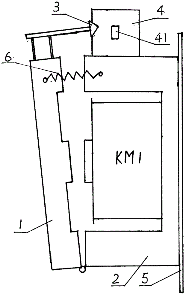
[0043] Such as figure 2 As shown, the chevron-shaped static iron core 2 with the contactor coil KM1 opens to one side and is fixed on the support plate 5. The moving iron core 1 and the static iron core 2 are hinged at the inner lower end of each other, and the three-phase moving contact Q 1 , Q 2 , Q 3 It is integrated with the moving iron core 1 in a linkage mode. The shaft of the lock hook 3 is fixed above the moving iron core 1, the fault-removing lock 4 is fixed above the static iron core 2, and the head of the bolt 41 of the fault-removing lock is close to A support spring 6 is installed between the moving and static iron cores on the center line of the lock hook 3 in a horizontal state. In this embodiment, except for the failure, the structure of the lock 4 is exactly the same as in Example 1.
PUM
 Abstract
Description
Claims
Application Information
 - R&D
- Intellectual Property
- Life Sciences
- Materials
- Tech Scout
- Unparalleled Data Quality
- Higher Quality Content
- 60% Fewer Hallucinations
Browse by: Latest US Patents, China's latest patents, Technical Efficacy Thesaurus, Application Domain, Technology Topic, Popular Technical Reports.
© 2025 PatSnap. All rights reserved.Legal|Privacy policy|Modern Slavery Act Transparency Statement|Sitemap|About US| Contact US: help@patsnap.com


