Universal swinging angle revolving light

A technology of angular rotation and rotating disk, applied in lighting devices, electric light sources, components of lighting devices, etc., can solve the problems of wire short circuit, wire winding, trouble in use, etc., and achieve the effect of simple use

Active Publication Date: 2012-04-18
广州市震泓科技股份有限公司
View PDF5 Cites 10 Cited by
  • Summary
  • Abstract
  • Description
  • Claims
  • Application Information

AI Technical Summary

Problems solved by technology

[0002] At present, the rotating and swinging lights can either only rotate but not swing, or can only swing but not rotate, and the use is relatively simple.
There are also lighting lamps that can swing and rotate, but they need to be operated manually, which is cumbersome to use. Moreover, these rotating and swinging lighting lamps cannot rotate continuously because of wire restrictions during rotation and swing, or continuous rotation will cause wires Winding and other problems, long-term use will easily lead to twisted and damaged wires, and serious wires will short-circuit

Method used


Image

  • Universal swinging angle revolving light
  • Universal swinging angle revolving light
  • Universal swinging angle revolving light

Examples


Embodiment 1

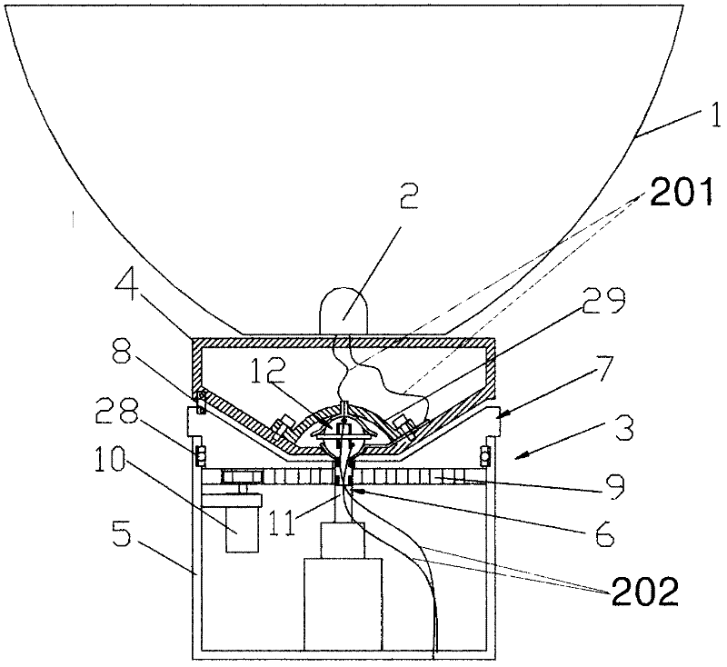
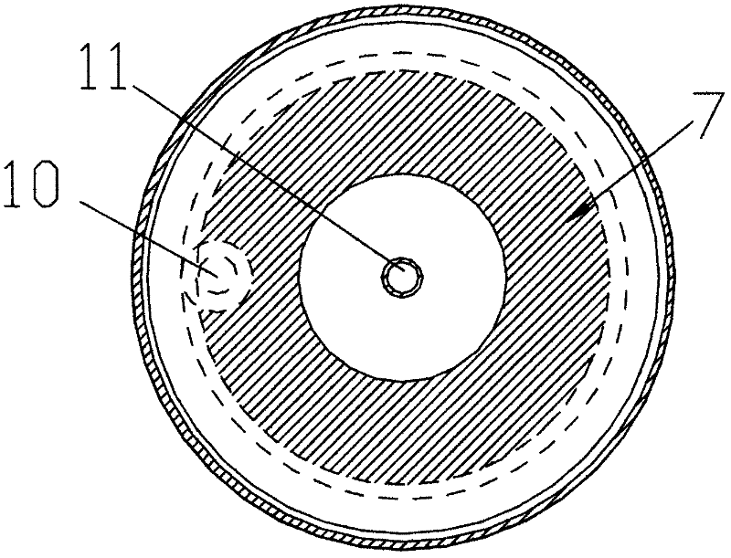
[0028] Such as Figure 1 to Figure 4 The shown universal pendulum rotating lamp includes a reflective bowl 1 , a light source 2 and a lamp holder 3 . The lamp holder 3 includes an upper lamp holder 4 and a lower lamp holder 5, the reflective bowl 1 and the light source 2 are fixedly installed on the upper lamp holder 4, and a lamp holder 4 is arranged between the upper lamp holder 4 and the lower lamp holder 5. A lifting device 6 that swings up and down and a rotating device 7 that makes the upper lamp holder 4 rotate. A connecting piece 8 is provided between the rotating device 7 and the upper lamp holder 4 to be movably connected with each other. The rotating device 7 is a rotating disk with a gear 9 installed on the lower lamp holder 5. A bearing 28 is fixedly fitted between the rotating disk and the lower lamp holder 5. A manual or remote control is fixed on the lower lamp holder 5 under the rotating disk. The motor 10 for operation is provided with a driving gear 10-1, ...

Embodiment 2

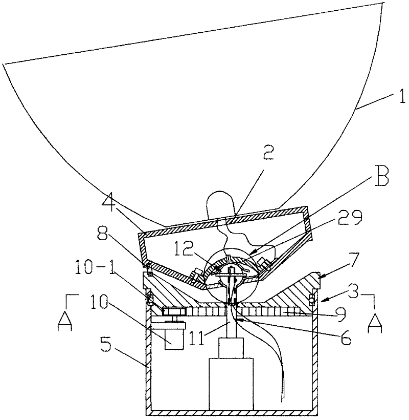
[0031] Such as Figure 5 to Figure 7 The top ball 12 of the shown universal pendulum angle rotating lamp is divided into an upper hemisphere 18 and a lower hemisphere 19, the upper hemisphere 19 and the lower hemisphere 20 are threaded, and the top ball 12 is arranged in the fixing frame 29 under the upper lamp holder 5, A round hole 29-1 is provided at the top of the center position of the fixing frame, and positioning holes 29-2 are arranged on both sides of the fixing frame. The top ball 12 is located in the round hole 29-1 to form a structure that can be pushed up and down. There is an inner cavity 20 inside the top ball. 20 is matched with a lead body 21 correspondingly, and the shape of the lead body 21 corresponds to the inner cavity 20 as a cylindrical boss body. Lead wire body 21 is provided with a positioning piece 21-1, and this positioning piece 21-1 is a movable swing positioning piece, and positioning piece 21-1 is a "∩" strip (such as Figure 6 and Figure 7 ...


PUM


Abstract

The invention belongs to the field of lamps and relates to an illumination lamp. A universal swinging angle revolving light comprises a reflection bowl, a light source and a lamp holder. The lamp holder comprises an upper lamp holder and a lower lamp holder; the reflection bowl and the light source are fixed on the upper lamp holder; a lifting device and a revolving device are arranged between the upper lamp holder and the lower lamp holder; and a connection piece is arranged between the revolving device and the upper lamp holder to connect the revolving device and the upper lamp holder. The revolving lamp can revolve continuously, and completely avoid the problems of winding of electric wires, and the irradiation angle can be adjusted.

Description

technical field [0001] The invention belongs to the field of lamps and relates to a lamp for illumination. technical background [0002] At present, the rotating and swinging lighting lamps either can only rotate but cannot swing, or can only swing but cannot rotate, so the use is relatively simple. There are also lighting lamps that can swing and rotate, but they need to be operated manually, which is cumbersome to use. Moreover, these rotating and swinging lighting lamps cannot rotate continuously because of wire restrictions during rotation and swing, or continuous rotation will cause wires Winding and other problems, long-term use will easily lead to twisted and damaged wires, and serious wires will short-circuit. Contents of the invention [0003] In order to solve the defects of the above-mentioned technology in the existing rotating and swinging lighting lamps, the present invention provides a universal swing angle rotating lamp that can rotate and swing, and compl...

Claims


Application Information

Patent Timeline
Patent Type & Authority Applications(China)
IPC IPC(8): F21S2/00F21V19/02
Inventor 胡宇峰
Owner 广州市震泓科技股份有限公司
Why Eureka
Try Eureka