

Portable working machine
A working machine, portable technology, applied in the field of shock absorbing mechanism, can solve problems such as trouble
Active Publication Date: 2012-05-02
HITACHI KOKI CO LTD
View PDF7 Cites 6 Cited by
- Summary
- Abstract
- Description
- Claims
- Application Information
AI Technical Summary
Problems solved by technology
Therefore, two different types of tools need to b
Method used
View moreImage
Smart ImageViewing Examples

Examples
 PUM
 Abstract
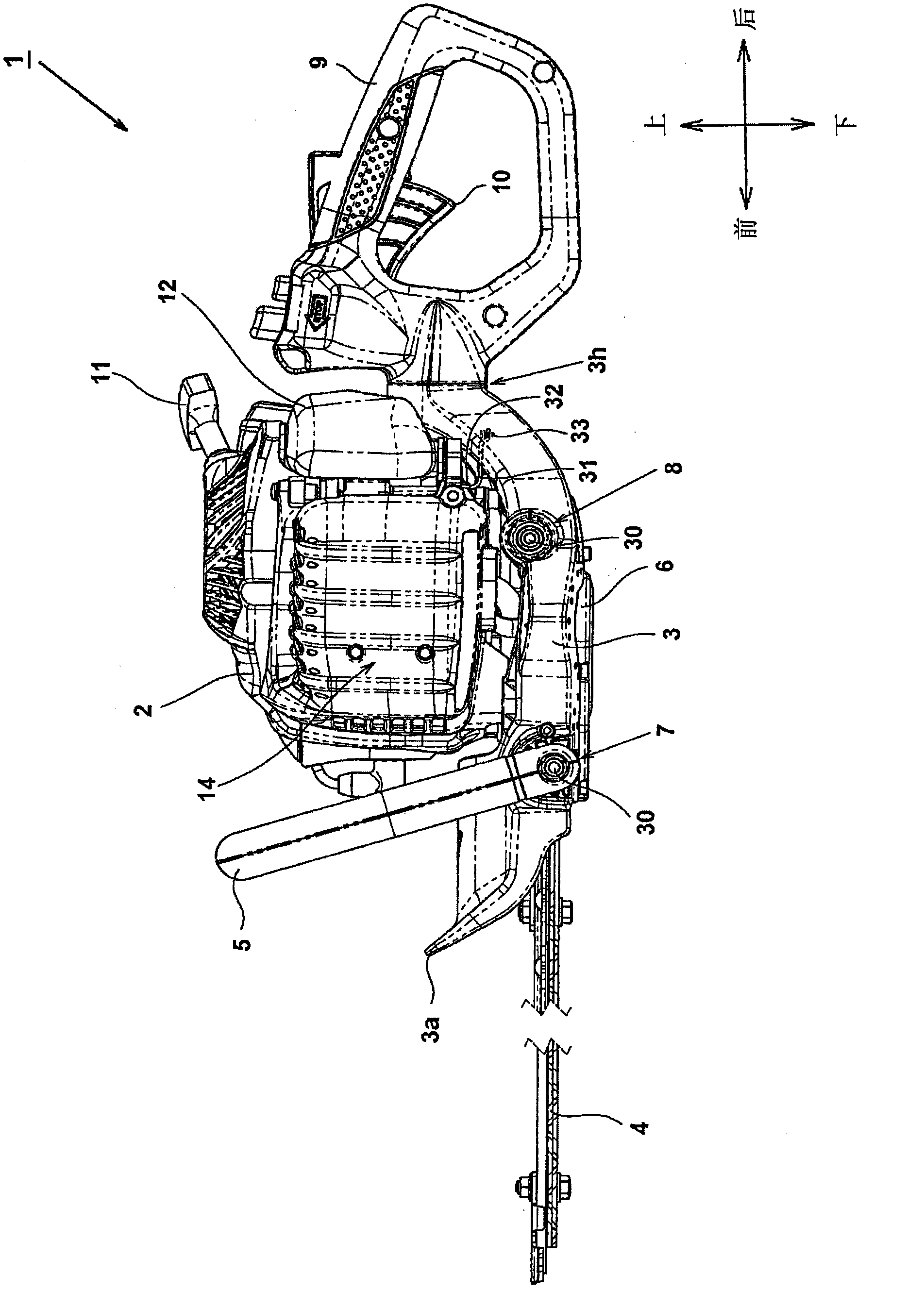
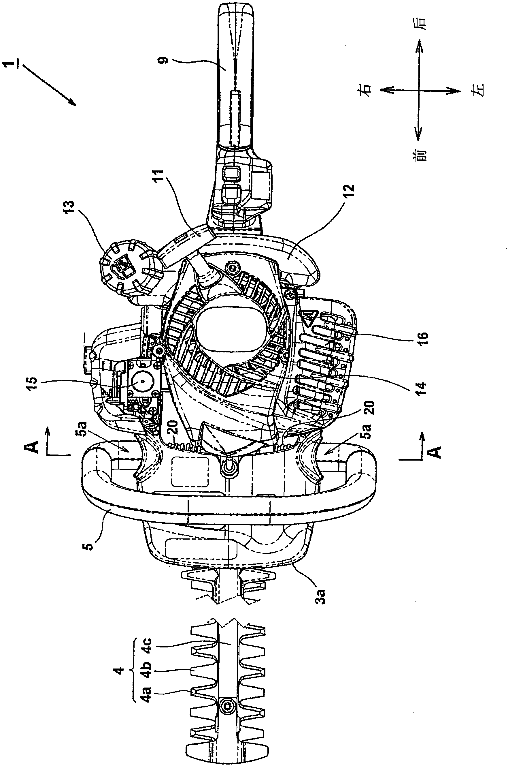
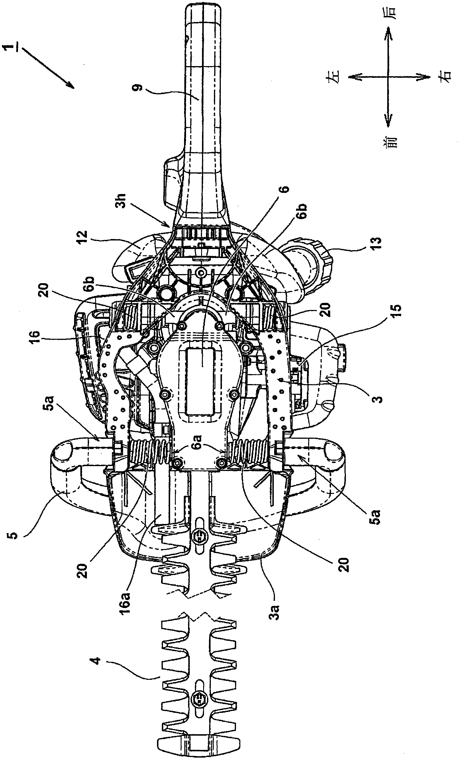
A portable working machine comprising: an engine; a frame which holds the engine; front handle and a rear handle which are provided to the frame; and a power conversion unit for transmitting an output from the engine to drive a working tool, wherein the engine, the power conversion unit and the working tool being held by the frame via an elastic member, and wherein the front handle and the elastic member are disposed so that an axis passing through a center of an attachment portion of the front handle and an axis passing through a center of an attachment portion of the elastic member substantially coincide with each other.
Description
[0001] Cross References to Related Applications [0002] This application claims priority from Japanese Patent Application No. 2010-218678 filed on September 29, 2010, the entire contents of which are incorporated herein by reference. technical field [0003] The present invention relates to a shock absorber mechanism in a portable work machine, and more particularly, to a portable work machine in which shock absorber parts and a power unit can be easily fixed. Background technique [0004] In portable work machines such as hedge trimmers (hedge trimmers), engines are widely used as power sources. Engines are advantageous in that, despite their small size and light weight, they are capable of obtaining a large output; and, with fuel supplied, they are capable of continuous operation for many hours. However, in an engine, a piston reciprocates in a cylinder and creates an explosion when the air-fuel mixture burns. Therefore, the disadvantage of an engine is that it generate...
Claims
Login to View More Application Information
Patent Timeline
 IPC IPC(8): A01G3/053
CPCB25B5/006A01G3/053B25F5/006
Inventor田村福志挂札晋一
OwnerHITACHI KOKI CO LTD